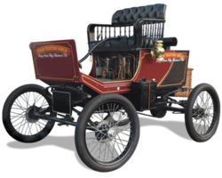

The 1899 Locomobile Steam Car Replica, known as the Lykamobile is a full scale live steam automobile manufactured in 24 kits. This kit is available from a company called "Steam Traction World" located in Daventry, United Kingdom. Each kit is to be manufactured and sent once a month for 24 months. However for cost considerations I have chosen to have my kits batched and dispatched in larger crates to the United States (Topsail Beach, NC).
Specifications:
• Length 7ft 2.6in • Height 5ft 3in • Width 4ft 7.1in • Weight 904 lbs.• Water Tank Capacity 12 Gallons • Fuel Tank Capacity 7.3 Gallons
Construction:
• CHASSIS Tubular steel fabrication, combination weld, bolted and silver solder.
• STEERING “Ackerman” design tiller steering.
• DIFFERENTIAL & DRIVE Spur gear differential similar to the original Locomobile, drive shaft and bearings.
• WHEELS & TYRES Single tube pneumatic, treaded.
• BREAKING SYSTEM Disc brake system.
• ENGINE 21/4" diameter, 3" stroke modified “Hackworth” valve gear.
• WATER FEED Twin mechanical pump.
• BURNER Fuelled by diesel.
• BOILER Multi Fire Tube, fully constructed and complete with necessary paperwork and inspected by notified body.
• BODYWORK & SEATS Wooden with steel frame, seating capacity of 2 persons, with turned decorative spindles with leather style upholstery.
• Gears: forward and reverse.
• Assemble with hand-tools only
• Step-by-step instructions
• Technical service and help-line backup
• Designed on ‘Solidworks’ CAD
• Manufactured on modern CNC machines for build accuracy and high quality
Thursday, February 25, 2021
Engine Packing Nut Modification

Saturday, February 6, 2021
Water Tank - Boiler - Bypass System
I don't know how many times I have had to trace the plumbing to figure out the water circuit for the filling of the boiler and the bypass valve. The bypass valve when open will provide a piping system that allows the pumps (that are mounted to the engine that pump all the time when the steam engine is running) to "bypass" the filling of the water into the boiler. This is important because the boiler should not be filled to the very top ever. The boiler needs some head space for the steam to be generated and pressurized. This pressurized steam is what is sent to the engine to be expanded to drive the pistons up and down. Below is a hand drawing/sketch of the system with the bypass valve open.
Popular Posts
-
As probably like some of the fellow Lykamobile kit builders, I have been studying this kit for sometime now. A Lyka Series 1 builder (jjtjr ...
-
Kit # 15 arrived mid January 2019 while I was away on our annual buying trip to Atlanta for our two retail gift shops here on Topsail Island...
-
Kit # 2 was pretty straight forward. The assembly of the oil impregnated bushings into the steering tube went well. The assembly of the stub...
-
So September 19, 2015 I discovered the Lykamobile Steam Car through some Google search I did and promptly sent an email to Dean Rogers Direc...
-
Finally got all those pieces parts painted and cured. Took a little while longer due the winter temperatures. My garage is heated, but it st...
-
I have decided to paint my Lykamobile similar to an 1899 Locomobile that was recently auctioned off by Bonham's this past year. Below ar...
-
Below is an image of what I have found to be one of my most important tools -- a half round needle file. Also used extensively were a ...


