
The first item was to install the reversing shaft bushings to the body frame boss. My bushings had a loose fit, so I used a little bearing sealant to fix them in place.

Next was to attach the Reverser Quadrant Bracket with four M6 Flat Head screws.

After letting my bearing sealant set up for a while, I assembled a thrust washer onto the brake handle and slid the brake handle into the boss.

Next was to assemble the Inner Brake Lever with a small key and fix this with a set screw. I had to adjust the depth of the keyway on the Inner Brake Lever due to a slight interference fit for these parts to slide together. I didn't want to force the parts together because I need to disassemble everything for final painting and finish.

Now the Reverser Lever is passed through the Brake Lever towards the Engine Support Frame and through the two bushing brackets.

Here we encounter my first fitting issue. As I have mentioned in a previous posting, the engine support frame is made from structural steel tubing. The tubing is not the best solution to rely upon for dimensional integrity. In the process of rolling the tubing into its rectangular shape at the steel manufacturing plant, there are inherent artifacts in that process that don't allow for nice square, parallel structure. Below you will see that the Reverser shaft is not parallel with the cross member frame. I took one measurement close to the Boss.

And then another measurement close to the brackets and as you can see below there is a significant difference -- about 0.080 inches (2mm).


Next I decided to unbolt the middle bracket from the engine support frame to see its alignment of the shaft through the remaining bracket.


Now the Reverser shaft measured parallel to the frame. So the issue mostly at this point is the middle bracket. A little "rat-tail" filing was in order.

Now comes my first encounter with the vagueness of the instructions. The instructions state to place the reverser lever between the two brackets with "a" 2mm washer (LK1475) on either side of the component. I did this and something didn't look right, too much slop!

At this point I consult Greg (fellow Lyka builder from France) because I know he had already completed Kit 15. He informed me that I was missing a few parts and set me straight. The assembly directions should have also instructed to use another 2mm washer LK1476 that has a slightly larger Outside Diameter (one is 30mm the other 32mm). The Reverser Lever actually has a 30mm side and a 32mm side diameter therefore matching washers. Also at this point I true up the engine support tube to make the brackets perpendicular and parallel to each other by filing the tube's rolled edge some.


Then the Bypass Rod Support Bushing is inserted into the Reverser Lever Shaft. I had to take about 0.001 inch off the diameter to get the bushing to a slide fit -- again I didn't want to force the fit.


Now I mount the brass reverser quadrant to the reverser bracket.

Next was to install the Reverser Rod Bypass Handle to the rod. I first try 15mm and test fit.

But I end up doing about 12mm.

And I used medium strength thread locker for the final assembly of the Bypass Handle to the rod.

This is now placed into the Reversing Lever Shaft and set with two M6 nuts (I had to use regular M6 nuts because my shipment of parts didn't have the half nuts (jam nuts) that were supposed to be sent. I will correct this in my final assembly with Stainless Steel hardware.

At this point I notice that the Parking Brake Lever will not fully seat into the brass quadrant. This will have to be corrected with a little filing of the lever in this area. When manufacturing and bending the lever to its specification, the steel actually deforms a little in this process which is easily fixed.


Onto mounting the ball valve and mounting bracket.

Another M6 nut is placed on the rod and a mating part that slides onto the ball valve stem and threaded to the rod is used. This part is referred to as the Bypass Actuator (LK1441N).

Now our instructions say to assemble the Reversing Rod that mounts to the Reversing Actuator and the Engine. It consists of two clevis', two threaded rods, a turn buckle or threaded adjuster and two M12 jam nuts (one left hand thread). The kit supplied regular M12 nuts, but I swapped them for some half nuts that I had.

The instruction says to loosen the engine reversing arm's set screws and rotate the arm so that the clevis can be installed. I chose not to do this at this time because I'm going to paint the assembly black. I did mount it to the reversing lever actuator for fit and slid the engine clevis over the engine reversing actuator as a test fit.

Valve Timing instructions were given in this kit, however Steam Traction World did not provide any means to hook up the engine by means of a manifold for compressed air as instructed for testing purposes. I skipped over this part and await parts in a subsequent kit before attempting to time the valves. Next the kit provided some of the parts for the lubrication system - again the instructions say to assemble and mount the lubricator, but no lubricator was supplied -- again this will follow in a subsequent kit. But the brackets and rod are mounted! (temporarily)

Finally this kit provided the cabling and parts for the Parking Brake.

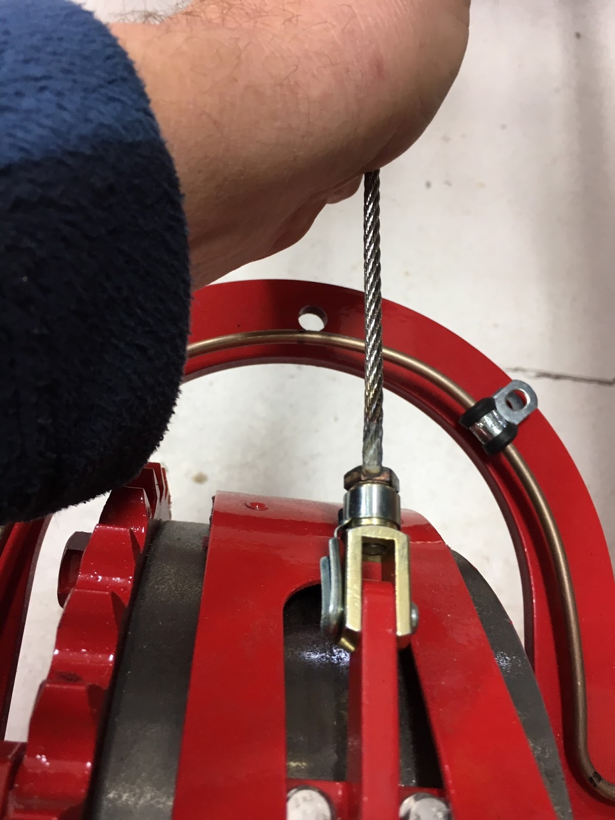
First is to assemble the cable to the differential brake pad.
Then to route the cable through the pulleys. Here I find a design issue with the placement of one of the spacers for the middle pulley bracket. I removed this one spacer and bolt to allow the cable to pass through this bracket unimpeded.

But you will notice that the cable still rubs against the upper part of the bracket.

Also I notice on the smaller brake pulley that is mounted to the side frame that it too was rubbing the cable.

Therefore grinding, filing, tapping a new M8 into the middle bracket for the third spacer will solve these issues.


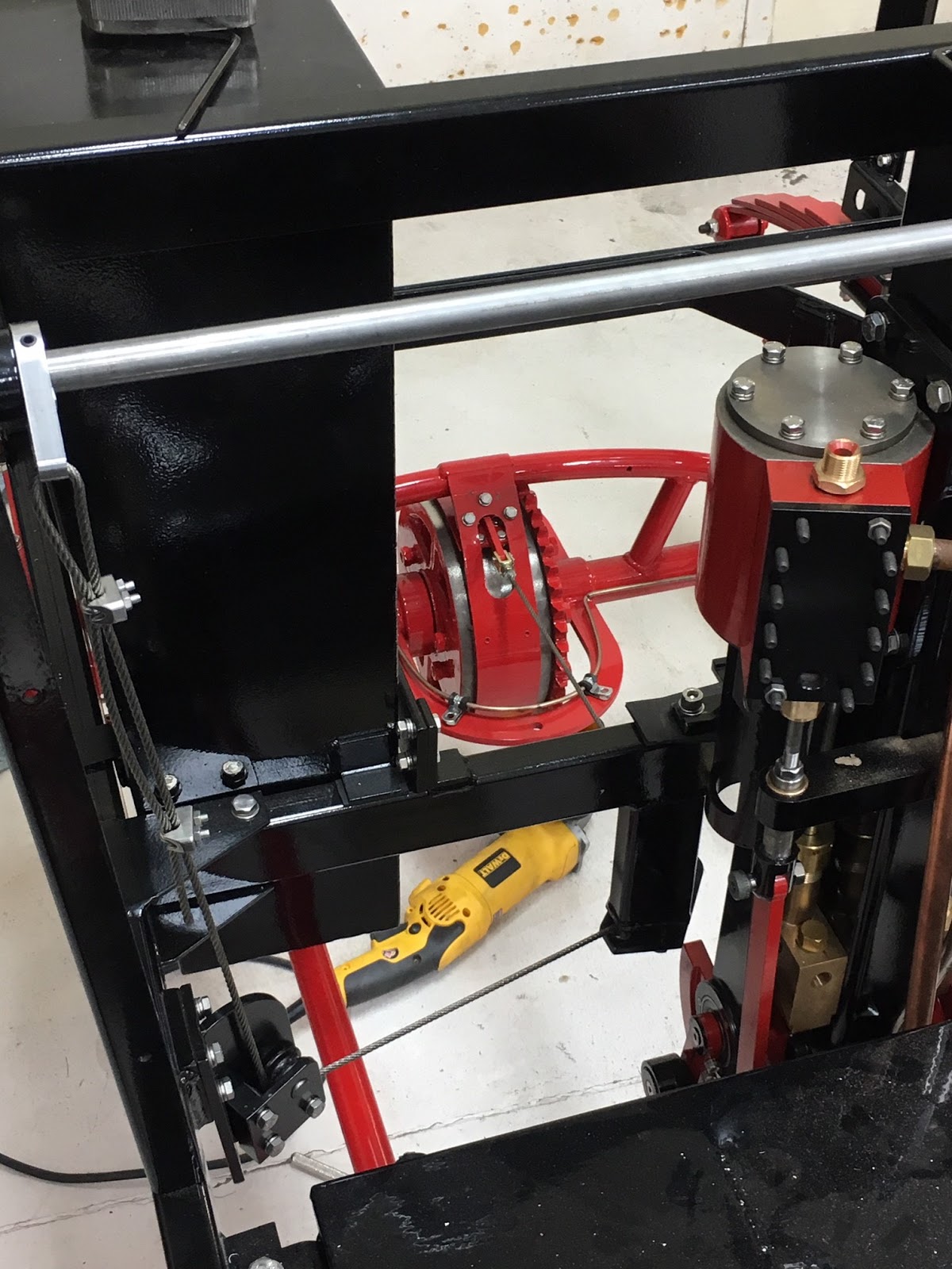
And a few final images of the brake cable assembled.


Now it is time to take all of this apart and paint everything that needs to be protected and reassemble. The next Kit 16 is another Boiler payment followed by Kit 17 the Boiler, so we think. I know Steam Traction World is busy welding the boilers, so hopefully it won't be too much longer before Kit 17 is ready for shipment.


Hi Greir,
ReplyDeleteMy name is Ian and I live in Tasmania, Australia. Been following your posts with much interest as I have a half built Lykamobile I purchased that I am trying to finish. But finding it very hard to obtain parts. Was particularly interested in your latest post on the reverser etc, as I want to work on this next. It seems that STW are very hard to get a response out of :( as they said some months ago when I inquired that they could help me out with some of the kits and kit 15 was one. I have the chassis, have started work on an original timber body, have a new 14" boiler and a (very) rough engine. But need so much more :(
Ian,
DeletePleased to see that STW have reached round the world as far as Tasmania - Good luck with the build.
Grier,
ReplyDeleteYour pictures are just as informative as ever, I am now following in your footsteps. With the misalignment of the reversing shaft and the mountings on the engine, I must have had a more severe problem of the same sort; I have put washers under the engine mounts to get the alignment needed. I shall check the parallelism as you have done - thanks. As I received the Reverser kit before I had fitted the engine, I fitted the lower section of the reverser connection clevis to the engine before it was put in place. I have noticed that the drawings are less accurate since Steve's demise - The instructions relate to the 2mm washers but not their slightly different diameters; also, releasing the set screws would not enable the fitting of the clevis, but the written instructions corrected that misinformation.
Regards, Alan.
Hi Alan,
ReplyDeleteWhat is probably not evident that I did for the mounting of the engine to the lower cross member of the Lykamobile frame was that I used a couple of pieces of rectangular rubber about 3 mm thick that I had laying around. This elevated my engine probably 2 mm or so (after compression). It may have helped my alignment issues some. My original thoughts were to try to isolate the vibration of the engine some, probably a futile attempt! If you look closely in the ninth picture you can just make out the rubber piece.
Best Regards too!
Grier
Here are a few things to think about, the water bypass lever is locked to the valve by double nutting it. The valve does not have a stop it just goes around. It is possible the lever and valve can get missed position this happened to me. Then you think your bypassing and your not, worse is you think your filling the boiler and your not. What I did was to install a stop on the valve it only goes 90 degs. I took it off another valve. On louvers mine were wood like yours but when filling the water tanks and you overfill them water will run down the sides of the car and warp the wood louvers. This happened to me, my fix was to made them from sheet metal.
ReplyDelete