The 1899 Locomobile Steam Car Replica, known as the Lykamobile is a full scale live steam automobile manufactured in 24 kits. This kit is available from a company called "Steam Traction World" located in Daventry, United Kingdom. Each kit is to be manufactured and sent once a month for 24 months. However for cost considerations I have chosen to have my kits batched and dispatched in larger crates to the United States (Topsail Beach, NC).

Specifications:
• Length 7ft 2.6in • Height 5ft 3in • Width 4ft 7.1in • Weight 904 lbs.• Water Tank Capacity 12 Gallons • Fuel Tank Capacity 7.3 Gallons

Construction:

CHASSIS Tubular steel fabrication, combination weld, bolted and silver solder.
STEERING “Ackerman” design tiller steering.
DIFFERENTIAL & DRIVE Spur gear differential similar to the original Locomobile, drive shaft and bearings.
WHEELS & TYRES Single tube pneumatic, treaded.
BREAKING SYSTEM Disc brake system.
ENGINE 21/4" diameter, 3" stroke modified “Hackworth” valve gear.
WATER FEED Twin mechanical pump.
BURNER Fuelled by diesel.
BOILER Multi Fire Tube, fully constructed and complete with necessary paperwork and inspected by notified body.
BODYWORK & SEATS Wooden with steel frame, seating capacity of 2 persons, with turned decorative spindles with leather style upholstery.
Gears: forward and reverse.
Assemble with hand-tools only
Step-by-step instructions
Technical service and help-line backup
Designed on ‘Solidworks’ CAD
Manufactured on modern CNC machines for build accuracy and high quality


Tuesday, February 25, 2020

Lyka Kit #24 - Seat Part 2

The next step for the seat was to cover the holes for the spindles for the seat base and armrest for painting. I purchased some 3/8 inch OD flexible plastic tubing and with a couple wraps of blue painter's tape, the tubing fit snug into the holes.


If you are counting that's 22 holes in the seat base and another 22 holes in the armrest. That's a lot of taping and cutting. Once this was completed, I sprayed painted them with gray primer.


I also sprayed the bottom side of the seat base too the next day. Once all of this was cured and with a light sanding of the pieces I sprayed them black.

The spindles have cured for over a week now and now I will attempt to paint the middle section red. I ordered some angled artist type brushes for this job. I first line the edges on each side by spinning the spindle with my left hand while holding the brush in my right hand, next turning the spindle over and repeating the lining of that edge and then painting the middle. This will require two coats to completely hide the black. The following pictures are just one coat.

 Halfway there - time for a break!


The next step is to assemble and glue the seat components together, however I may repaint the armrest and seat bottom after some sanding. The grain of the wood is a little pronounced and maybe the paint did not flow all the way into the grain or possibly the grain soaked up the paint. Either way it might be good to take the time to sand it down and repaint. All depends how I feel in the next couple of days. Lyka Kit # 24 Part 3 will cover the gluing of everything.

Thursday, February 20, 2020

Lyka Kit #24 - Seat Part 1

Steam Traction World sent on all the wood components for the seat. The upholstered seat bottom and back rest will be dispatched at a later date. The first thing in order was to dry fit the seat base. This comprised of four pieces of wood.
 
 
All joints were glued with indoor/outdoor wood glue. I chose a brand available at our local Lowes Building Supply store. It is called Titebond III Ultimate.
I secure the pieces with some furniture pipe clamps and corrugated cardboard to guard against accidentally marring the wood seat base sides. Any excess glue is wiped off with a damp cloth.
Next is to dry fit all of the seat spindles. I quickly discover that one end of the seat spindles are a bit bigger and will not fit into the seat base or armrest. So I carefully use my belt sander to rotate the spindle and sand away the diameter a little bit at a time and keeping the contour or slope correct by eye, testing the fit as I go until satisfied. I repeat this 22 times!
Next to dry fit as many of the components as possible. This turns out to be a "whack-a-mole" exercise. Just as you get a few spindles seated, and try a few more the previous spindle pop out! However eventually with experience you learn how to control all those spindles.


As you can see the armrest has not been glued together yet. I wanted to test the dry assembly before gluing anything. Below I have aligned the armrest pieces and am satisfied that they will be correct once glued.
Steam Traction World suggests that you glue the armrest together before wood screwing the pieces together. I could only do one side at a time, so this took two days to accomplish. This is a butt assembly and I used some other wood clamps to secure the pieces butted together with glue.


Once the glue has cured (24 hours each side) I dry fit the armrest again. Steam Traction World supplied some test wood pieces that are cut to the proper spacing that the armrest should be to the seat base. All looks good to go.
After much thought about how to paint this beast, I decided that I would paint all the pieces individually, masking off the places where the glue goes to assure wood to wood gluing. I figured I could obtain a better finished result by spray painting the pieces individually and then assembling versus brush painting the whole seat assembled looking for drips and runs from the brush. Time will tell if I made the right decision! So the first thing I need is a set up to paint the 22 spindles. I created a fixture from lumber (again from Lowes Building Supply store) that would space out the spindles and allow me to rotate the spindles for complete painting coverage.
As you can see I have masked off each end with painter's tape to the depth that the spindle goes into the seat base or armrest. Any areas that happen to be exposed once assembled I will touch up with a small art brush and paint. I sprayed two coats of primer (12 hours drying time each - so two days to accomplish this).

Then I allowed this to dry another 24 hours before spray painting all of them black.

I will let these dry for a few days. I plan on painting the center knob red to match my chassis color. I have ordered a variety pack of small sizes of angled paint brushes - about $10 from Amazon.com. While I wait for the brushes, the paint has to cure anyway. Next I return to the armrest to assemble the wood screws to secure the glued butted pieces. Steam Traction World suggest that you drill a pilot hole for the screw. The wood is a hardwood, and the last thing you would want is to have the would split from screwing the screw into the armrest or the screw to shear off. Unfortunately I don't have a long enough and small enough drill bit to do this. So once again Amazon.com comes to the rescue - none of my local resources had the drill bit. The drill bit is 1/16 inch diameter by 6 inches long.
I figured out how far I need to drill into the armrest and mark this off with painter's tape. Because the wood is hard you must clear the bit a few times as you go.
Once the blue tape reaches the edge of the slotted opening I will be at the proper depth. Next I screw the wood screw into the armrest. All of this is repeated for the other side.
And the final finishing touch is to glue the wooden plug into the armrest to hide the screw.


And wipe the excess glue off and let it all cure.
In my next posting I will cover the sanding and finishing of the seat bottom and armrest, I expect that I will have to fill in a few places with wood filler and sand this smooth, then prime all the pieces and paint them black. Then once the spindles are painted with the red, I can assemble and glue everything together. Stay Tuned!

Thursday, February 6, 2020

Lyka Kit #18 Cladding and Burner Tray Part 1

With this kit we will finally place the boiler on the chassis and begin the process of insulating the boiler, burner tray and smoke hood. Unfortunately I will only be able to mount the burner tray under the boiler due a redesign of the "Stays" that holds the burner tray up to the boiler. This will be further explained later in this post. But first various pipe fittings need to be placed on the actual boiler. Below I have gathered the various parts for the underside of the boiler.
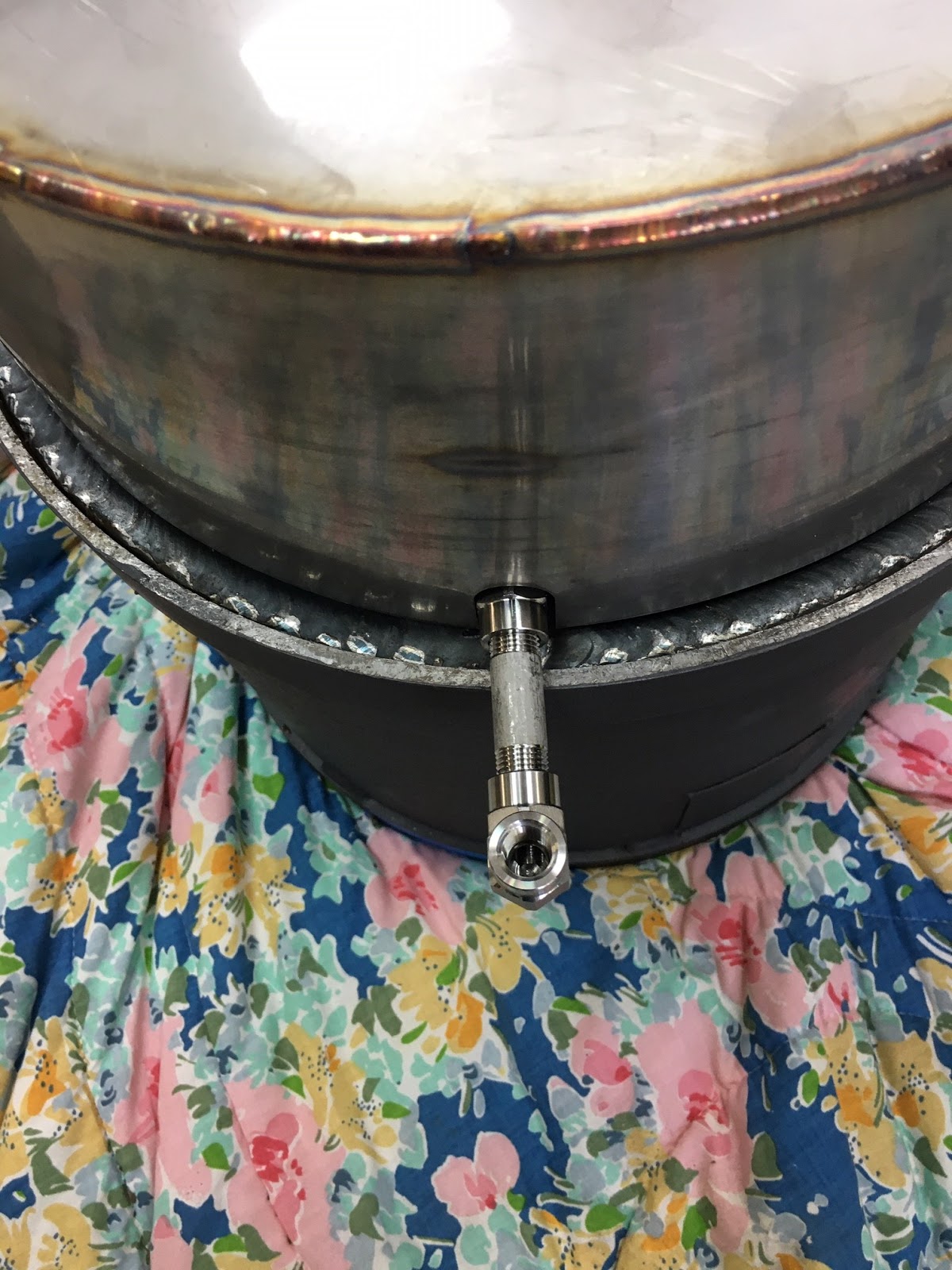
These fittings are temporarily mounted on the boiler so that their angular orientation passing through the burner tray parts can be determined. Below are pictures of the boiler orientated upside down for this work and the burner inner tray placed on top to align the pipe fittings.


At this point I mark the outer rim of the boiler on each side of the protruding pipe as an alignment guide for the permanent fitting of the pipes. Next I use the Steamseal compound to help seal the fittings and tighten all the fittings tight on the bottom of the boiler.


Now I gather all the parts for the top of the boiler.

It can't be seen in the below picture, but the boiler is sitting on a dolly that keeps the installed fittings from being damaged.

Again I loosely fit all of the fittings on the top of the boiler and place the inner smoke hood loosely on top of the boiler to orientate the fittings.


This time I mark the pipe locations with a paint pen on the outer boiler edge. Again I use the Steamseal on the fitting threads and fit them to the boiler.


Now comes the exciting part - placing the boiler into the chassis. I made a boiler platform out of rectangular tubular steel to be used with my engine hoist. However the platform must be oriented in one precise way that allows the platform to pass through the frame that ultimately holds the boiler.

Steam Traction World instructs that the front of the boiler must be tilted up to allow the burner tray assembly to pass over the hand brake bracket. I place a 1 inch x 1 inch tubular steel piece on the forward mounting flange to accomplish this in a safe manner.
The boiler is resting on the three mounting flanges with the tubular steel section keeping the boiler elevated for later fitting of the burner tray.


Next is the assembly of the inner and outer burner tray with the superwool insulation. First I mount the spacers on the outer side of the inner tray.
Then I place the superwool insulation in the inner side of the outer tray.
Next I place the inner tray into the outer tray and install some superwool that I thought was the correct piece.
The above piece of superwool is not the correct piece. There was no diagram given in the instructions, so it was sort of a puzzle figuring our what pieces went where. Below are the correct pieces. I had to use a paint stirring stick to help slide the superwool into the inner and outer burner trays.
The use of a tapered alignment tool was required to manipulate the sheet metal to allow for the superwool to slide into the opening. It was also useful for fitting the bolts into their holes too.

Finally the last sheet metal part is fitted. I'm adding split lock washers where I can to help secure the nuts and bolts from becoming loose through any vibrations that might occur under steam power.

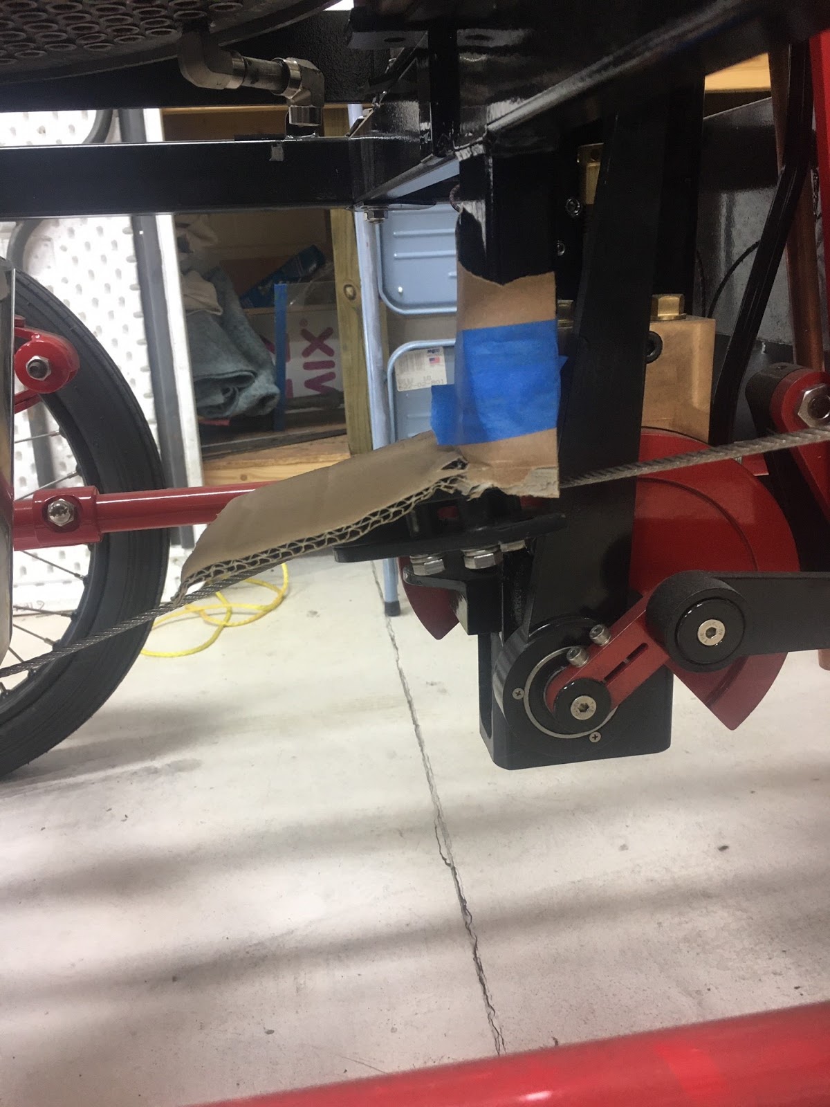
Next is the placement of the burner tray under the boiler. To help protect the paint finishes, I use some wool mat over the rear and a piece of heavy cardboard on top of the handbrake bracket.

The burner tray assembly is slid into place, resting on the handbrake bracket and the rear-end.


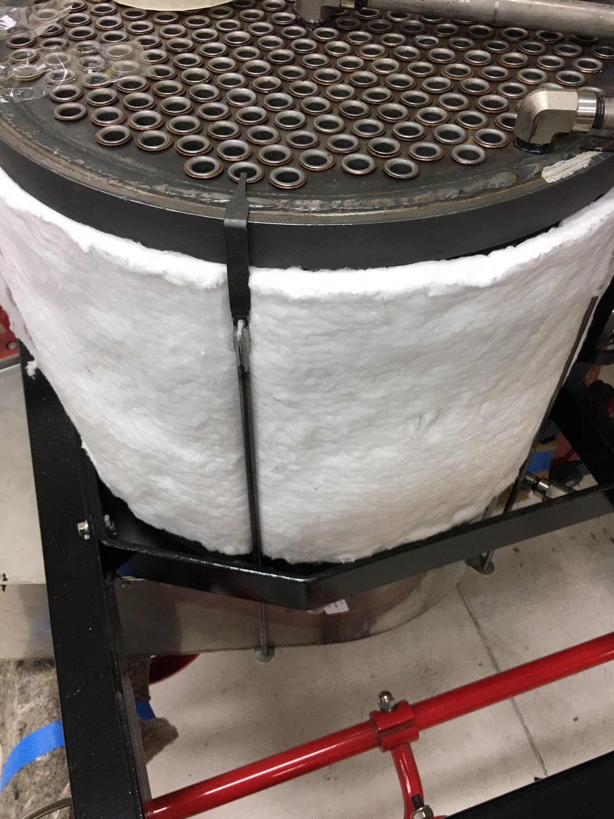
Next is placing the superwool insulation around the boiler and fixing it in place with the boiler Stays. These are the rods that are hung on the boiler, pass through the three boiler support mounting flanges and through the burner tray mounting brackets. An M6 nut is used to lift the burner tray up and against the underside of the boiler.


When raising the burner tray to the boiler by screwing the M6 nuts up, care must be taken to make sure the burner tray slips inside the boiler inner ring. Because sheet metal fabrication can be imprecise, the burner tray needs to be pushed, beat, cajoled into submission with my plastic hammer, various flat bars etc. The below pictures shows where the parts must slip to be fitted properly. This is looking up at the bottom side of the boiler.
Don't try to just use the M6 nuts to compress the burner tray into the boiler. The Stays are very weak and will bend. This is the part that Steam Traction World is redesigning to be more structurally sound. Next I place the two front boiler cladding pieces for trial fitting.
Next I place the inner smoke hood on top of the boiler for fit.

The inner smoke hood is supposed to slip down over the outer diameter of the boiler. Again because this is a sheet metal fabrication, the smoke hood is not very round and much time was expended manipulating the smoke hood over the boiler. It is a fairly tight fit. I also had to widen a few of the pipe slot clearances by using a Dremel tool fitted with an abrasive cutting disc to slice off additional sheet metal for clearance. Once satisfied with the pipe slot clearances, I tap the inner smoke hood over the boiler with my plastic hammer using a few small screw drivers as guides or shims to help align the sheet metal over the boiler flange. Now it is time to work on the outer smoke hood. I mount a few of the spacers that hold the inner and outer sheet metal apart for the superwool and fit the outer smoke hood onto the inner smoke hood on the boiler. Many of the pipe openings had to be enlarged. It appears that the pipe clearances were cut for the pipe diameter, however (at least for my kit) I need clearance for the elbow fittings. So again I use my Dremel to cut away the sheet metal to get the clearance that will be needed.

Satisfied now with the clearances, I can assemble the two smoke hood pieces and superwool insulation. Below is a picture of the spacers mounted on the inside of the outer smoke hood.
The superwool insulation is placed inside the outer smoke hood.
I then use cellophane tape to fix the superwool insulation around the outer circumference of the inner smoke hood.
This is then slipped inside the outer smoke hood and M6 nuts and split washers are used to complete the assembly.
This is as far as I can go until I receive the new and improved redesigned 'Stays' that Stem Traction World has promised. To continue assembly of all the outer sheet metal cladding would be wasted effort because they would have to be disassembled to replace the redesigned 'Stays'. Once I receive the 'Stays' the final assembly will be covered in Lyka Kit #18 Cladding and Burner Tray Part 2. Below are a few pictures of the partial completion of kit #18 and the Lykamobile.


Popular Posts