This is the final kit for the steam engine. Once complete it should look like this:
The first step of assembling the reversing shaft is to press into the main bearing housing the reversing shaft Oilite bronze bushings. I chose not to disassemble the main bearing housings from the support tube and used a medium sized C-Clamp.
The reverser shaft was fitted by loosening the main bearing housing Socket Head Screws for alignment, however I discovered that due to the structural tubing, perfect alignment was not possible. I had to very slightly open up the bronze bushings. Also each bushing was filed flush with the cast bracket.
Now the shaft rotates nicely.
To install the reverse linkage arm one of the main bearing assemblies will need to be removed.
The reversing shaft with the middle key installed is then placed into the remaining main bearing assembly and the reversing linkage placed on the shaft. The uninstalled main bearing assembly is then reinstalled. Some additional filing on the reverse linkage was required to allow the shaft to rotate without being pinched between the two main bearing assemblies. At this point I install the outer Reverser Arm #1 on each end and reinstall the crank shaft and connecting rod. This time I use thread lock on the crankshaft.
This portion is now assembled.
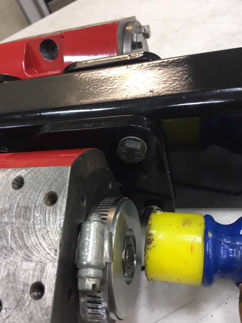
Next the Return Crank Arm is assembled on the end of the crankshafts. The keys needed to be shortened (by way of my electric grinder).
The Return Crank Arm is a very tight fit. Steam Traction World advises that this arm needs to fit snugly because it drives some heavy components. I had to use my plastic hammer/mallet to drive the arms onto the crankshaft.
The Return Crank Arm has two tapped holes on the side. Steam Traction World fitted these with two M5 cap screws to provide additional clamping pressure to keep this arm secure. (I need to install them). Next the Valve Chest assembly studs are installed into the Steam Cylinder.
Then the Valve Chest fittings are installed with Foliac Sealer brushed on the threads.
The Gland Nuts are loosely fitted to the brass nipples and the Valve Rods inserted.
Four jam nuts are used to cradle the Slide Valve. You first thread two jam nuts all the way down the Valve Rod keeping them loose, then you fix two jam nuts tight to the very end of the Valve Rod, then you need to slip the Valve Slide into the Valve Chest cradling the Valve Rod. Tighten the two loose jam nuts onto the Valve Slide and then back off these two jam nut just enough to allow the Valve Slide to drop away from the Valve Rod. You want a slide fit between the four jam nuts. The Valve Slide must not be locked in place but allowed some "float".
At this point you need to check to see if the Valve Slides slide freely inside the Valve Chest. I had to dress the sides a little with a flat file to get a nice slide feel. I didn't file much off, I think it was more of a removal of some machining marks.
Place both Valve Chests over the studs on the Steam Cylinder and use two M6 nuts on each Valve Chest place diagonally to keep the Valve Chest secure for the steps to follow after assembling the remaining linkages on the Crankshaft and Reverser Shaft.
Next is to install the two Oilite Bushings into the Valve Guide. My Valve Guide Bracket holes were a slide fit instead of a press fit. I had to use the Bearing Grade Sealant to fix them into the Valve Guide Bracket.
Because this sealant takes time to set, I decided to move on to the next challenge. Next I install all the bushings and bearings into the Radius Rod.
These are installed on the Return Crank along with the Reversing Arm #2 (red) that is also fixed to the Reverser Arm #1 (black).
A few more images for clarity.
Now back to the Valve Guide Assembly. The bearing grade sealant has set up and this bracket is installed on to the main support tube.
The two Valve Stems are placed into the Valve Guide Bracket. They are like clevis' where the Valve Crank will be fixed to it by M10 shoulder bolts. But first these Valve Stems need to be threaded to the Valve Rods. If you look closely you can see that the threaded Valve Rod alignment is not good. Following are close ups of the misalignment.
Attempting to thread the Valve Stems on to the Valve Rods will completely bind up the mechanism. The issue here is that the support tube/structure is not very true. A better fabrication method I would have chosen if this was a true production vehicle. But its not, and this is a hobby. So much fiddling and fitting is required. I decided that I needed to flatten out the main tube some by filing.

I did align the Cylinder Head Mounting Brackets as best I could, but the Valve Guide Bracket still would not line up. The Valve Guide Bracket was actually twisting when bolted securely to the Support Tube. I filed the Support Tube a bit more trying to eliminate this torsion. In the end I had to shim one side of the Valve Guide Bracket 0.005 inch on the other side 0.013 inch. Also ultimately I had to sand off a little on the diameter of the Valve Stems due to the fact that the threaded hole in the Valve Stem was slightly off center with the outer diameter. When I threaded the Valve Stem in the bronze bushing to the Valve Rod I could tell it was off-center because it would get tight on one side as I threaded the Valve Stem -- it was wobbling in the bronze bushing.

You should be able to slide the Valve Stem through the Valve Guide pushing the Valve Rod and Valve Slide in the Valve Chest by hand. Next was to assemble the Valve Crank. The Valve Crank end was about 0.020 inches bigger than the clevis portion of the Valve Stem. I had to belt sand away the Valve Crank to get a nice slide fit.
Once this was done I pressed in the bronze bushings into the Valve Crank and assembled the Valve Cranks to the Valve Stem and Valve Rod.
Final check of the assembly is to see if everything connected moves freely by hand.
The last steps for this kit is to mount two brackets for the Reverser Actuator that will follow in a later kit and the copper Exhaust Pipe. I did polish the ends some to remove the oxidation from the soldering of the fittings, but this will eventually oxidize again in use.
Now that everything is assembled, I will take it apart some to re-paint some of the brackets and parts that were messed up and scratched from the fitting and assembly process and then once re-assembled mount the engine in the frame for safe keeping.
Can't wait for the next kit !!!