The 1899 Locomobile Steam Car Replica, known as the Lykamobile is a full scale live steam automobile manufactured in 24 kits. This kit is available from a company called "Steam Traction World" located in Daventry, United Kingdom. Each kit is to be manufactured and sent once a month for 24 months. However for cost considerations I have chosen to have my kits batched and dispatched in larger crates to the United States (Topsail Beach, NC).

Specifications:
• Length 7ft 2.6in • Height 5ft 3in • Width 4ft 7.1in • Weight 904 lbs.• Water Tank Capacity 12 Gallons • Fuel Tank Capacity 7.3 Gallons

Construction:

CHASSIS Tubular steel fabrication, combination weld, bolted and silver solder.
STEERING “Ackerman” design tiller steering.
DIFFERENTIAL & DRIVE Spur gear differential similar to the original Locomobile, drive shaft and bearings.
WHEELS & TYRES Single tube pneumatic, treaded.
BREAKING SYSTEM Disc brake system.
ENGINE 21/4" diameter, 3" stroke modified “Hackworth” valve gear.
WATER FEED Twin mechanical pump.
BURNER Fuelled by diesel.
BOILER Multi Fire Tube, fully constructed and complete with necessary paperwork and inspected by notified body.
BODYWORK & SEATS Wooden with steel frame, seating capacity of 2 persons, with turned decorative spindles with leather style upholstery.
Gears: forward and reverse.
Assemble with hand-tools only
Step-by-step instructions
Technical service and help-line backup
Designed on ‘Solidworks’ CAD
Manufactured on modern CNC machines for build accuracy and high quality


Saturday, June 20, 2020

Lyka Kit #23 Bodywork Panels Part 1

Its time to start working on the floor panels. The main floor panel has a few cut-outs to allow access to the battery switches and fuel tank. These areas are reinforced with sheet metal and also provides a lip to allow the placement of some wood pieces to cover the holes. We got the battery door, but the round fuel access was not sent in this kit. The only trick here is to place the sheetmetal carefully so that when you drill the pilot holes for the screws they are equidistant from the edges making the exposed lip/ledge consistent.


All of this will be removed for painting later. Next I placed the two support boards on the chassis frame to see how they line up. I notice that a few hex head bolts and some of my wiring gets in the way. I adjust the wiring eyelets, but the hex head bolts are causing an interference with the board laying down. This requires slotting the board a bit deeper at each slot.


Now the slotted board lays flat across the cross member. 
I measure the distances between the two supporting boards on the frame and transfer these dimensions to the underside of the floor board for drilling and fixing the boards.


All assembled and test fitted on the frame as shown below. 
The Next task is to get the top boards to fit between the two side boards. This requires removal from the angled edges some material. I utilize an orbital sander with 120 and 220 sand paper. This is a trial and error process until the boards slip in-between the two side panels.
The all fitted, now it is time to sand, prime and paint.

Final sanding is done with 220 grit sandpaper. 

The next image shows the use of some body filler to fill in the flat head screws and other little chips etc. Once cured all will be sanded down smooth and painted. I put two coats of primer on with sanding between coats.
For the top panels, Steam Traction World instructs that we need to locate and drill our own mounting holes. They provided brass flat head screws that can be counter sunk and made flush with the top of the boards. This method will be good for the panel that sits below the front seat, however I'm going to deviate from the recommendation and use for the rear top board some brass slotted pan head screws. I will polish the heads bright. Also Steam Traction World supplied wing nuts to use, my thinking is to drill and tap the top frame members and forget about the wing nuts. Below are images showing my approach.

I discovered that the weldment below was causing the top board to lift up. A little grinding and some black touch-up paint solved that issue.
As a note to any other Lykamobile builders, the recommended dimensions for laying out the above holes I modified to suit what I thought would be best, I did note that one dimension they recommended would have placed the hole very close to the edge of the cross frame member. They had a 240 mm dimension, I used 250 mm.

Part 2 will cover the final assembly for Lyka Kit 23.

Friday, June 19, 2020

Lyka Kit #20 Burner Test Firing

Just a quick posting. Today I purchased some diesel fuel and put in about 2 gallons for testing. The Tank is supposed to hold 6 gallons, but no need to fill it up now. The setup directions for the burner state for a number 2 -  60 degree nozzle the damper needs to be set at the #5 position. I'm assuming I have a number 2 nozzle because there was an empty plastic tube in the kit box marked with #2-60 degrees. The Steam Traction World directions make no mention of this fact. Setting the damper is simple enough, the images below are self explanatory.


The next challenge was priming the fuel lines. I first tried to rely on the burner vacuum pump, but the system kept on cutting out thinking there was no fuel - which there wasn't. I could see this would take quite a bit of time if you kept on resetting the system so I decided to prime things the old fashion way. I took the fuel filter apart and poured some diesel into it, then took off the fuel line at the burner and siphoned by mouth the line - don't care much for the taste of diesel ! But that did the trick, tighten everything back up and fired the burner off. Below is a movie showing the operation. A fair amount of oil residue from the parts started to burn off. I think it needs a few more firings to clean everything up.
 

Thursday, June 18, 2020

Lyka Kit #23 Bodywork Side Panels

Well I was hoping to not drill any more holes into my finished side panels, but I decided that to make a secure attachment of the forward sections would be best. Listening to Jim Trotta (Series 1 Lykamobile) on a YouTube video he posted, he suggested that over time bolting the side panels would crack the paint due to the bolt compressing the wood area. His solution was to press and flare some copper tubing in the side panels that the bolt would go through and provide the necessary structure to securely bolt the side panels without compressing the wood. That gave me inspiration to think about a different way to accomplish most of what Jim did. I settled on Brass Binding Barrel Bolts found at McMaster Carr.
The length would need to be cut to about 34 mm to provide the correct fit through the side panel and wood blocks etc. But first I layout the blocks and position them. You need to be careful with the angular wooden blocks. I noticed that the side frame welds protruded some preventing the blocks to lay flat. A little grinding and touch-up paint solved that problem.


Positioning of the angular blocks required a little sanding of the block on the interface of the wood to the metal frame. I kept testing the floor boards until I was satisfied with the locations of the angular blocks. The floor board lays on the angular piece without and wobble or gaps side to side.
Now it is time to drill some pilot holes into the wooden blocks. I mark the blocks and then use a small drill bit first.

Then I place these blocks back into position and drill a pilot hole by using the drilled block hole as a guide from the back side of the panel.


Now I drill the proper size hole (slide fit) for the Binding Barrel from the front side of the panel.
I will later paint the blocks and the interiors of the holes for weatherproofing. Now after cutting the Binding Barrels to 34 mm, they are inserted and using a brass pan head screw and washer tighten everything up. The Binding barrel slightly compresses the side panel and bottoms out against the metal frame flange. I did polish the heads of the Binding Bolts a bit, my wife likes the brass, I may paint them black to hide them a bit. I'll decide that later after a while.


The final images all done.

Wednesday, June 17, 2020

Lyka Kit #20 Burner

Kit #20 involves the mounting of the burner, fuel line, filter and electronics. I first started with the fitting that goes into the tank. Steam Traction World I have found with their female pipe threads are typically tapped too deep - meaning the taper on the pipe thread is a bit big making it a challenge to get a proper seal. Usually you can crank down of the thread, but here the thread is loose all the way until the fitting bottoms out. I don't care for that, but hopefully the aviation form a gasket sealer will provide a sealed connection. Below is the part that goes into the tank.

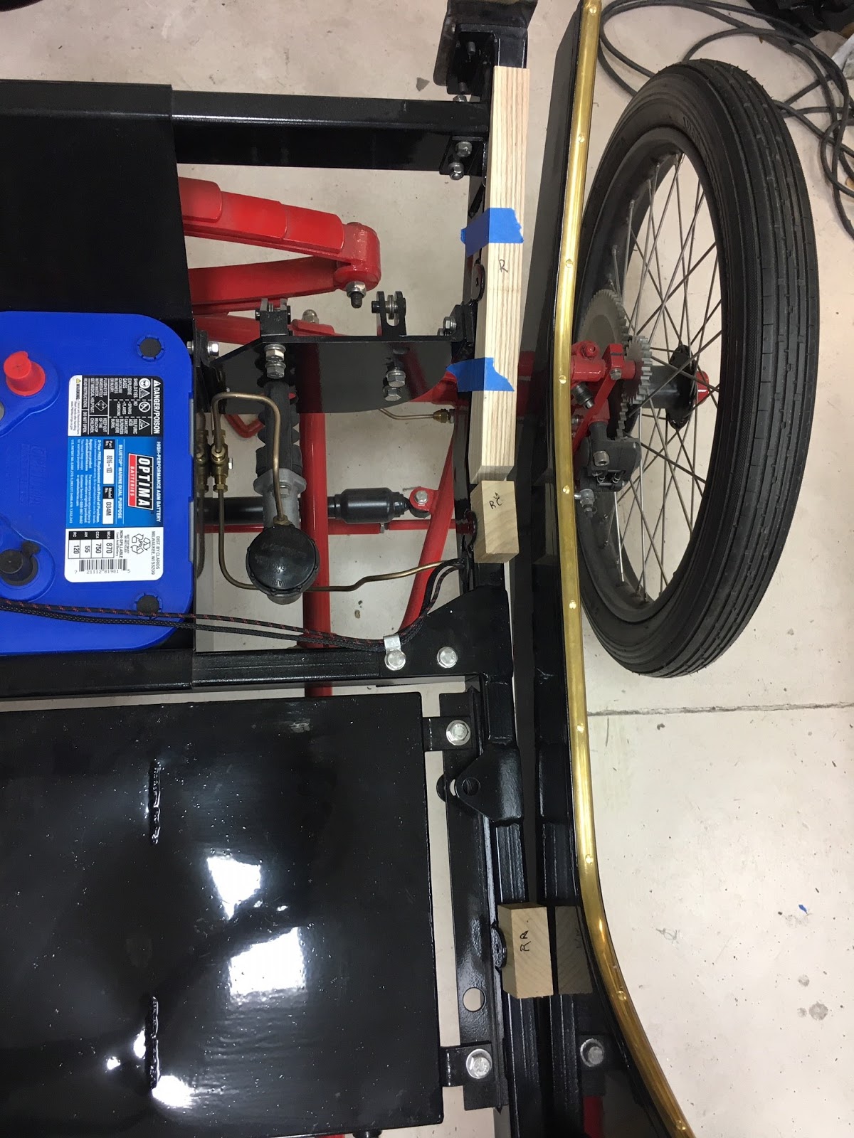
Next the copper fuel line is installed on the tank for fitting of the filter bracket and filter. I line up the copper pipe as best as I can, parallel to the boiler bracket, tucked towards the boiler so that is will not interfere with the water tank and clear it hoping that I can avoid it rattling on the side of the water tank once installed. The filter bracket mounting holes must be drilled out to mount it on the cross frame bracket.

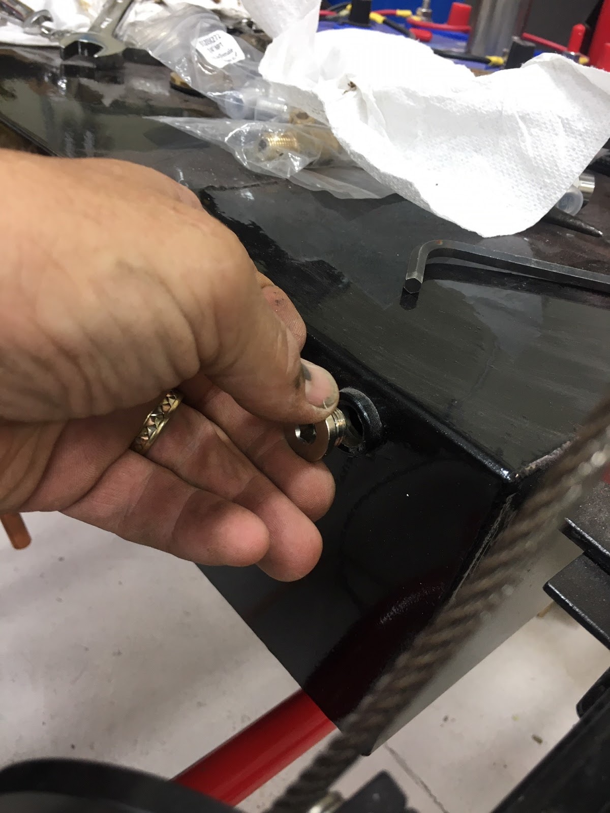
Next I install the vent plug on the top side of the fuel tank.

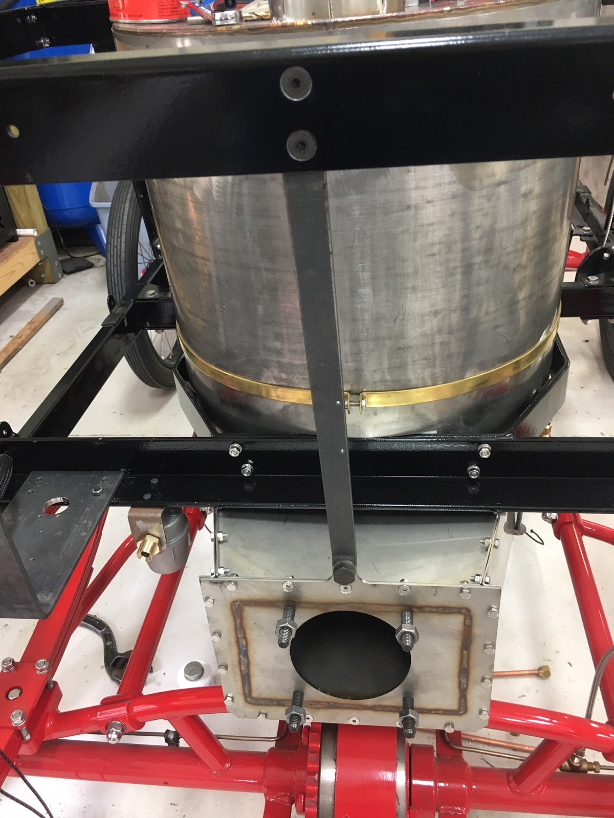
Then the supporting bracket for the burner is mounted to the sheet metal burner pan assembly.


The aluminum flange that interfaces with the burner pan and the burner is marked to where I need to grind away some of the flange for clearance of the M10 hex head bolt.

I decided to Dremel out the slot instead of cutting the bracket completely to the slotted hole. Makes for a stronger bracket, not that it is really needed, but looks better in my opinion.


Next I have to file the soft gasket that goes between the aluminum bracket and the burner pan. The gasket is very friable and care must be taken to not damage it.

The bolt studs have to be cut to allow for the mounting of the burner assembly. 
Test fitting the burner I notice that there still is a bit of a interference with one of the studs. So I mark the area and will Dremel out a bit of the aluminum bracket.


Now I focus on the mounting of the electrical power inverter. The inverter is supposed to be screwed on to the inside left rear side panel. I decided like with the boiler pressure switch that I was not going to mount anything to the interior sides of the panels if at all possible. So I devise a bracket that will allow me to mount the inverter to the frame with the side panel untouched. The side panel will be used as one side to keep the inverter in place. The painter's stirring stick below is there temporarily only as a means to keep the inverter in place until I mount the side panel.
 
Next is the wiring of the connector, mounting of the connector and plugging in the burner to the inverter. I found it easier to take the connector apart a bit (red and black components) to allow better gripping and maneuverability.

One side of the connector is mounted to the burner support bracket. 

 Here the connector is all assembled with the connector covers installed.


Through discussions with fellow Lykamobile Builder Greg Powell, I decided to take his advice concerning a fuel shut off valve. Steam Traction World did not consider placing one in the system, and for a bit of safety I believe it is a good idea to have one. The easiest place to put a valve is at the tank. I did a little research and found a three way valve from McMaster Carr. Follow this link: Valve # 46095K51. However I need to modify it a bit and put the copper extension tube on this valve. I first have to unsolder the tube from the original fitting.

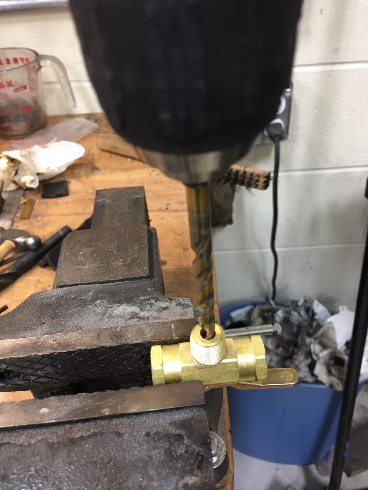
 Then drill out the new fitting to allow the 1/4 inch copper tube to be inserted and re-soldered.

One side of the diverter valve will be plugged with a 1/4 inch pipe plug. This will prevent me from accidentally opening it up, but still allow me the ability to drain the tank in the future by taking the plug out. Below the valve is installed with the plug and the original fitting in the valve to connect the copper tube. Again unfortunately I couldn't crank the fitting all the way as I would have preferred because the fitting bottomed out on the tank. This required me to cut the copper pipe and bend it to meet the valve. I purchased a ferrule to hopefully seal the pipe.
The other modification I did came from reading Justin's Steam Car Build blog. Much as he didn't like holding the burner to the aluminum flange with one bolt, neither did I. I decided to make a flange that would utilize the opposing M10 thread that Justin used. My approach is a little different than Justin's. My thinking is to make a small right angle flange that I will mount to the burner.

I realize that an M10 hex bolt mounting this flange would interfere with the M8 Hex Nut that would fix it to the aluminum flange. So I believe an M10 Flat Head Screw would work, try finding an M10 Flat Head Screw in the USA. All My local sources had screws going up to M8 and to order just one screw online is cost prohibited. Not to be deterred, I made a transition piece from the end of a M10 bolt by drilling and tapping an M8 thread into the end of the bolt and cut this off to be inserted into the M10 burner hole. See below.


Now I can use an M8 Flat Head Screw. Some countersinking was required to get the Flat Head to fully seat on the bracket.
It was a little tricky getting the M8 nut and washer threaded, I was even later able to get a split lock washer and regular washer on it after I painted the bracket for final assembly (no picture).

I feel much better about having the burner mounted with two bolts. The final assembly below.

Popular Posts