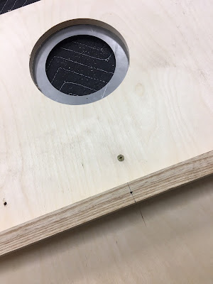
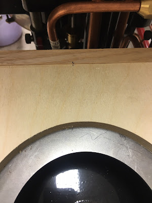
I discovered that the weldment below was causing the top board to lift up. A little grinding and some black touch-up paint solved that issue.

The 1899 Locomobile Steam Car Replica, known as the Lykamobile is a full scale live steam automobile manufactured in 24 kits. This kit is available from a company called "Steam Traction World" located in Daventry, United Kingdom. Each kit is to be manufactured and sent once a month for 24 months. However for cost considerations I have chosen to have my kits batched and dispatched in larger crates to the United States (Topsail Beach, NC).
Specifications:
• Length 7ft 2.6in • Height 5ft 3in • Width 4ft 7.1in • Weight 904 lbs.• Water Tank Capacity 12 Gallons • Fuel Tank Capacity 7.3 Gallons
Construction:
• CHASSIS Tubular steel fabrication, combination weld, bolted and silver solder.
• STEERING “Ackerman” design tiller steering.
• DIFFERENTIAL & DRIVE Spur gear differential similar to the original Locomobile, drive shaft and bearings.
• WHEELS & TYRES Single tube pneumatic, treaded.
• BREAKING SYSTEM Disc brake system.
• ENGINE 21/4" diameter, 3" stroke modified “Hackworth” valve gear.
• WATER FEED Twin mechanical pump.
• BURNER Fuelled by diesel.
• BOILER Multi Fire Tube, fully constructed and complete with necessary paperwork and inspected by notified body.
• BODYWORK & SEATS Wooden with steel frame, seating capacity of 2 persons, with turned decorative spindles with leather style upholstery.
• Gears: forward and reverse.
• Assemble with hand-tools only
• Step-by-step instructions
• Technical service and help-line backup
• Designed on ‘Solidworks’ CAD
• Manufactured on modern CNC machines for build accuracy and high quality
Saturday, June 20, 2020
Lyka Kit #23 Bodywork Panels Part 1
I discovered that the weldment below was causing the top board to lift up. A little grinding and some black touch-up paint solved that issue.
Popular Posts
-
As probably like some of the fellow Lykamobile kit builders, I have been studying this kit for sometime now. A Lyka Series 1 builder (jjtjr ...
-
Kit # 15 arrived mid January 2019 while I was away on our annual buying trip to Atlanta for our two retail gift shops here on Topsail Island...
-
Finally got all those pieces parts painted and cured. Took a little while longer due the winter temperatures. My garage is heated, but it st...
-
I have decided to paint my Lykamobile similar to an 1899 Locomobile that was recently auctioned off by Bonham's this past year. Below ar...
-
Kit # 2 was pretty straight forward. The assembly of the oil impregnated bushings into the steering tube went well. The assembly of the stub...
-
So September 19, 2015 I discovered the Lykamobile Steam Car through some Google search I did and promptly sent an email to Dean Rogers Direc...
-
Below is an image of what I have found to be one of my most important tools -- a half round needle file. Also used extensively were a ...


No comments:
Post a Comment