The 1899 Locomobile Steam Car Replica, known as the Lykamobile is a full scale live steam automobile manufactured in 24 kits. This kit is available from a company called "Steam Traction World" located in Daventry, United Kingdom. Each kit is to be manufactured and sent once a month for 24 months. However for cost considerations I have chosen to have my kits batched and dispatched in larger crates to the United States (Topsail Beach, NC).

Specifications:
• Length 7ft 2.6in • Height 5ft 3in • Width 4ft 7.1in • Weight 904 lbs.• Water Tank Capacity 12 Gallons • Fuel Tank Capacity 7.3 Gallons

Construction:

CHASSIS Tubular steel fabrication, combination weld, bolted and silver solder.
STEERING “Ackerman” design tiller steering.
DIFFERENTIAL & DRIVE Spur gear differential similar to the original Locomobile, drive shaft and bearings.
WHEELS & TYRES Single tube pneumatic, treaded.
BREAKING SYSTEM Disc brake system.
ENGINE 21/4" diameter, 3" stroke modified “Hackworth” valve gear.
WATER FEED Twin mechanical pump.
BURNER Fuelled by diesel.
BOILER Multi Fire Tube, fully constructed and complete with necessary paperwork and inspected by notified body.
BODYWORK & SEATS Wooden with steel frame, seating capacity of 2 persons, with turned decorative spindles with leather style upholstery.
Gears: forward and reverse.
Assemble with hand-tools only
Step-by-step instructions
Technical service and help-line backup
Designed on ‘Solidworks’ CAD
Manufactured on modern CNC machines for build accuracy and high quality


Tuesday, November 10, 2020

Lyka Kit #22 Final Kit - Part 2

Steam Traction World is supposed to be sending us Steaming Instructions that have not been written up yet, so being a little impatient I decided to hookup my air compressor to the inlet feed pipe which is located on the top of the boiler. This is a 3/8" pipe thread that will eventually be plugged once the first initial fill of water is done. I set the air pressure to 100 psi. Below is a video of the engine running in reverse. The engine uses a modified Hackworth Valve Gear and per the design the engine actually runs smoother in reverse. I suspect the engine has more power in forward though. I used some Chevron Meropa 680 gear oil for the steam oil. Still waiting to hear from Steam Traction World for a specification on the proper oil to use.

Very exciting to see the engine run at last !!

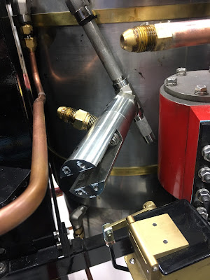
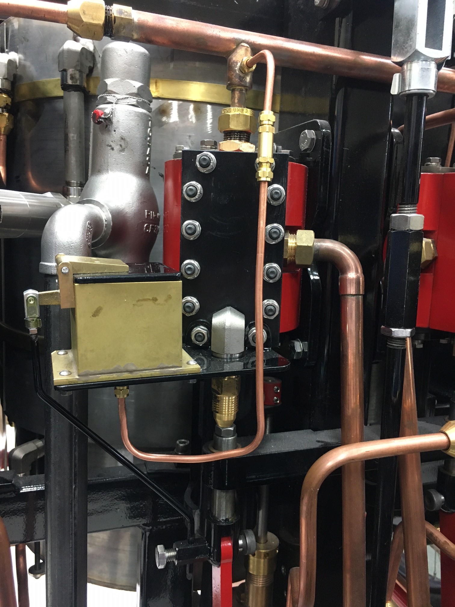
Now that I have the system pressurized I can start to chase down any leaks. Plain old dish washing soap and water is applied to all the fittings. I notice a few leaks here and there. One leak is at the interface between the two components for the throttle regulator valve.
I tried to use the Steam Seal Joint compound and this did not work. The threads are straight threads. I had to resort to High Temperature Silicone Gasket Maker - this did work.


I had a leak at the pressure gauge and this was solved with one rotation of the pressure gauge. Also I can hear inside the boiler at the inlet feed pipe a small leak. I had problems with this pipe fitting/thread and I suspect that the pipe thread was over cut and the taper was a bit too small. I will monitor this once the boiler is up to temperature to see if the expansion of the boiler seals the leak. It is a small leak and possibly won't be an issue with steam. I have also notice small leaks around the interface of the valve chest bolted to the cylinder blocks and again I will monitor this. It would be a big job disassembling to apply another amount of steam sealant there. All of the leaks so far have been very minor.

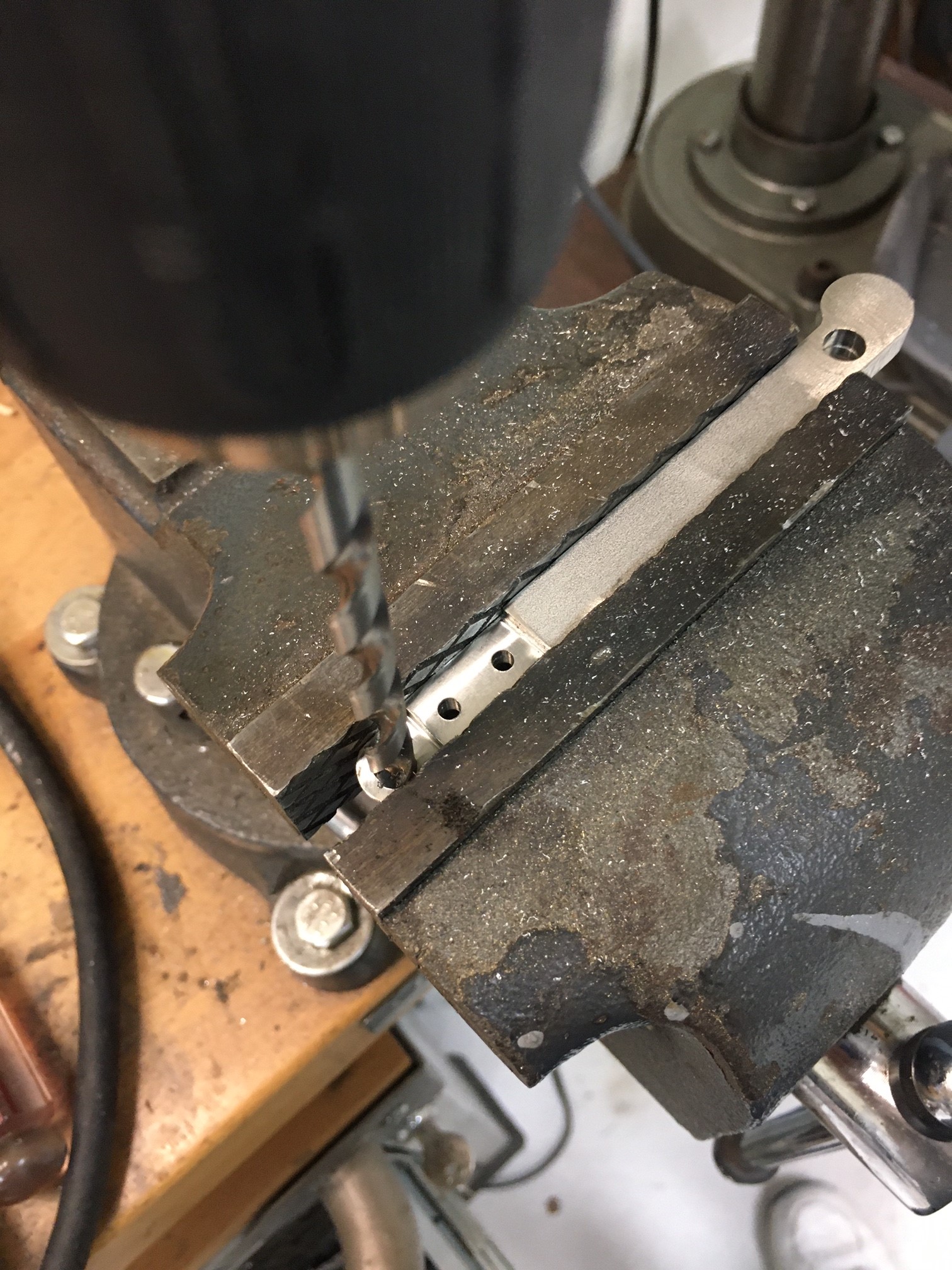
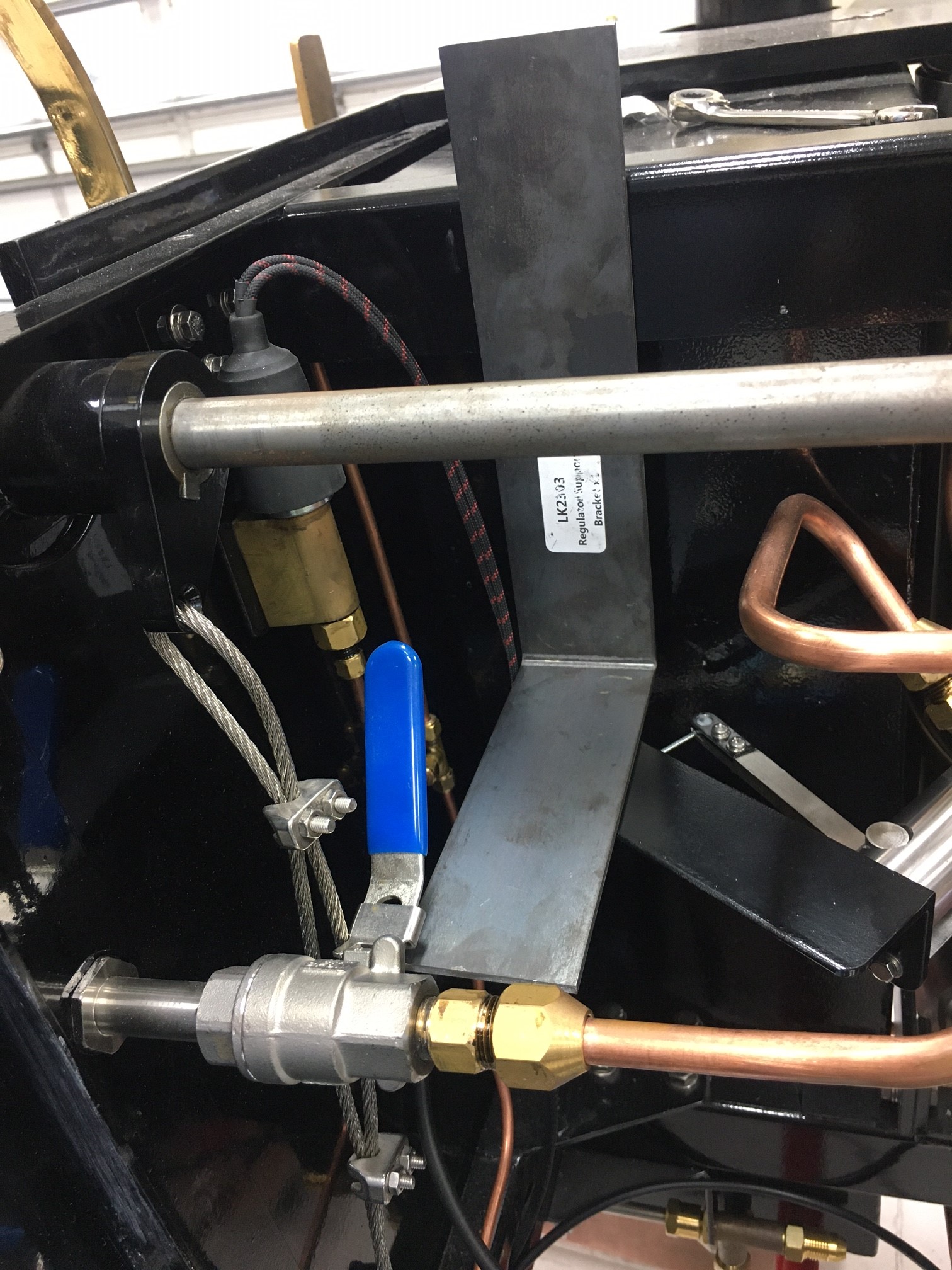
Next I decided that I was not too thrilled with the way Steam Traction World mounted the cylinder blow-off valve. This valve is mounted to the backside of the main floor board with 4 lag bolts. Any time that you want or need to take the floor board out would necessitate disassembly of the 4 lag bolts from underneath the chassis. My solution was to make a bracket and mount the valve to the frame. Below are the images for this.


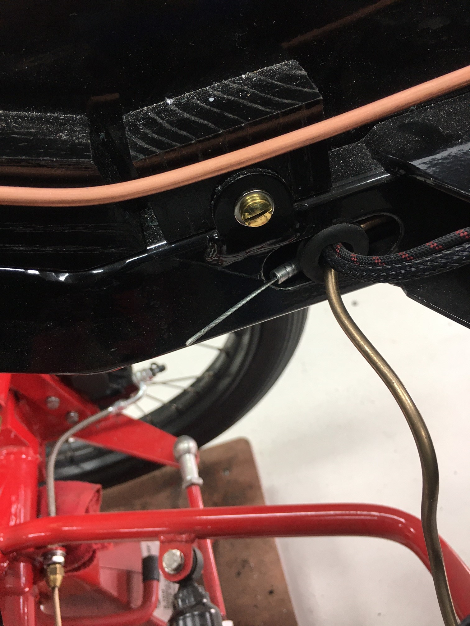
The cross bar bracket is bolted to the frame and is flush with the frame. I used flat head countersink screws. And finally for this update, the last item was to secure the 1/4 inch copper tubing that goes to the pressure gauge to the frame. A simple strap was made and I used a frame cross-member bolt to secure it. I felt that this was necessary to prevent a rattle. No doubt I probably wouldn't be able to hear it, but I eliminated it anyway.
And one last detail: I hooked up the chain and decided that I needed to get an offset link (half link). The chain is just a tad too long (by a half link), so I will have to take a full link off the chain and then use the half link to reduce the slack. Without this, the chain would be slapping around beating "things" up.
Trials and Tribulations Part 2 will be final details for the floor boards. 

Sunday, November 8, 2020

Lyka Kit #22 Final Kit - Part 1

The final kit arrived November 4, 2020. I signed up for the Lykamobile February, 2016. My first posting on this blog was October, 2017 with my first 7 kits arriving December 2017 (Kit #1 was actually ready January 2017). So it has been four years and nine months from committment to getting the final kit (minus one basket that will be mounted over the burner sent at a later date from Steam Traction World) and if we start counting from when I got my first batch of kits, it has been two years and 11 months of actual building the Lykamobile. 
This next posting isn't part of the last kit. It shows the final hook-up of the Speedometer Cable from the front modified brake disk to the speedometer. I had some leftover leather and I fashioned a flexible fitting to hold the speedometer cable conduit. Below are images.
Kit # 22 all unpacked, parts checked and ready to go.
My first task was to sort out the placement of the pressure gauge. Steam Traction World suggested to mount the pressure gauge to the angled floor board because they felt mounting the pressure gauge to the dash board would result in a lot of vibration making the gauge difficult to read. That may be true, but in the original Locomobile, the gauge was mounted vertically towards and in front of the right side of the dash. Because I have created a little dash, I am going to mount the pressure gauge on it. The copper tubing sent by Steam Traction World regardless where the pressure gauge is mounted needed to be carefully re-bent due to it being bent up for placement in the shipping box.
The instruction don't really say where the pressure tube is connected, however the only logical place for it could go is to the T-Fitting on the Pressure Switch mounted on the right side panel of the body. 

The copper tubing is formed and placed to the general location for my pressure gauge on my small dash. I layout the location to mount the brass fitting with the supplied paper template. I drill the appropriate sized holes and mount everything.
I came across an original Locomobile Steam Pressure gauge that I will use instead of the one supplied in the kit. I will fashion a few tie-downs for the copper tube to keep it from rattling around on the chassis in the future. Next I install the throttle control cable.
This involves taking the cable out from its protective sleeve, mounting the cable guide bolt and threading the cable through the cable guide bolt.
Now you are supposed to put the round plug into the throttle actuating arm. In my case the round plug was just a few thousands of an inch too big. I had to open the throttle actuating arm hole up a bit with a properly sized drill bit.
Next I replace the protective outer cable sleeve onto the cable and fish the cable through the chassis towards the accelerator pedal.
Next I mount the cable bolt guide and thread the cable through it towards the pedal.
The pedal hardware and spring return bracket and spring are mounted next and adjusted.
Steam Traction World has made a design change and has instructed us that an additional supporting bracket is needed to beef up and reduce the possible vibrations that might occur to the steam throttle regulator. The following images depict the work and mounting of the new bracket. First the throttle cable flange needs to be temporarily unbolted. 
Next the flange is set in position for marking, hack sawing, drilling and mounting.
Of course this bracket will need to be painted. The next task is to mount the sight tube for the water tanks. In my case because I have mounted a pair of lights to the sides of the Lykamobile body, this necessitated a bit of a challenge. Unfortunately the sight tube location was interfering with the side light and I had to bend and move the sight tube forward to avoid the lamp. No worries it all worked out as seen below.
Now for final assembly.
The next task was to assemble the pressure relief valve and fittings. I guess hindsight is always clearer, but boy would it have been good if we had received all of this in a much earlier kit. I hate doing negative work and on top of this Steam Traction World failed to provide the Isometric Drawing showing how the parts should go together. Not that anyone could figure this out, but it should have been included with a bit more instructions. Below are the parts laid out showing how it should be fit together.
Now all that work on the steam throttle cable, steam regulator needs to be disassembled to allow access to where the pressure relief valve goes. As you will see, the piping from the boiler will need to be moved over so that the elbow can be screwed on. Also the steam throttle will need to be removed completely to allow the pressure valve to be screwed on too. See the images below:
My next task is to fit the oiling tubing that goes from the oil pumps to the valve chambers. This is pretty straight forward but a big word of caution - make sure you assemble the one way check valves the correct way. The valves have no markings to show the way the oil flow should go. You have to blow on one side of the check valve to verify the direction and then not confuse the direction when you assemble everything. I had them backwards at first and this would have been disastrous if left. No oil to the valves/pistons would not be good. Double check your work.
The final work on the plumbing is to install all the tubing for the blow-off valves.
I test assembled everything first for fit and discovered that the Isometric Drawing for two of the parts was wrong. Steam Traction World made a design change, but failed to update the drawings. Once I figured this out everything went together with only slight adjustments to the tube bends.
The next few images shows where the drawing was wrong. Below is how the two copper pipes should be assembled to this valve. Steam Traction World had completely different looking parts in the drawing and had the copper pipe's locations reversed.
The final assembly I used the Teflon Tape on the brass T fitting. Hopefully this is correct to do. I don't expect the temperatures to get that high here, so it should be okay.
The final blow-off valves are fitted to the boiler. Unfortunately way back when Steam Traction World sent us some of the boiler fittings they used a fine thread fitting. Later they decided to replace these fittings with a coarse thread. I thought I had replaced all the fittings, but I discovered much to my chagrin a fitting that had not been changed. And this fitting required me to lift the right tank up to access it. I probably would have had to lift the tank up anyway to tighten the copper pipe attachment anyway - AGAIN negative work. Below are the images for this exercise.
And a final picture of all the plumbing completed !!
The very last thing to do is to figure out the Chain Tensioner. Steam Traction World had nothing in regards to instructions or drawings for this except a note that directions were to follow. But how difficult could this be? Below are the parts test fitted.
This assembly should be mounted between the engine frame and the differential frame. The following shows it test fitted on the Lykamobile.
I believe in the above photo that the nut should be the jam nut instead of this regular nut and that the protruding stud should be cut flush with the jam nut. The chain passes over this area and it would be catastrophic for the chain to catch on this protruding stud. I guess I will wait for instructions from Steam Traction World in this regard. 
My next posting will be showing an air pressure testing of the engine and a few additional modifications to the mounting of one of the blow-off valves and miscellaneous other details.

Popular Posts