The 1899 Locomobile Steam Car Replica, known as the Lykamobile is a full scale live steam automobile manufactured in 24 kits. This kit is available from a company called "Steam Traction World" located in Daventry, United Kingdom. Each kit is to be manufactured and sent once a month for 24 months. However for cost considerations I have chosen to have my kits batched and dispatched in larger crates to the United States (Topsail Beach, NC).

Specifications:
• Length 7ft 2.6in • Height 5ft 3in • Width 4ft 7.1in • Weight 904 lbs.• Water Tank Capacity 12 Gallons • Fuel Tank Capacity 7.3 Gallons

Construction:

CHASSIS Tubular steel fabrication, combination weld, bolted and silver solder.
STEERING “Ackerman” design tiller steering.
DIFFERENTIAL & DRIVE Spur gear differential similar to the original Locomobile, drive shaft and bearings.
WHEELS & TYRES Single tube pneumatic, treaded.
BREAKING SYSTEM Disc brake system.
ENGINE 21/4" diameter, 3" stroke modified “Hackworth” valve gear.
WATER FEED Twin mechanical pump.
BURNER Fuelled by diesel.
BOILER Multi Fire Tube, fully constructed and complete with necessary paperwork and inspected by notified body.
BODYWORK & SEATS Wooden with steel frame, seating capacity of 2 persons, with turned decorative spindles with leather style upholstery.
Gears: forward and reverse.
Assemble with hand-tools only
Step-by-step instructions
Technical service and help-line backup
Designed on ‘Solidworks’ CAD
Manufactured on modern CNC machines for build accuracy and high quality


Sunday, June 10, 2018

Lyka Kit #11 Pedal Ass'y-Brake Lines-Master Cyl. Part 3

The last part of Kit 11 entails the assembly of a pulley system for the parking brake and the mounting of the brake and accelerator pedals. Below is the Steam Traction World isometric drawing showing the two pulleys. The drawing shows the cable that will be attached to a hand operated lever. The cable and lever will be sent in a future kit.
The assembly is pretty straight forward. The Central Pulley Bracket is shown assembled below:
And the Side Pulley Bracket parts:
As you can see below from the test assembly of the parts a little modification is needed due to the bracket weldment interfering with the assembly. The part that holds the small pulley that is bolted to the bracket is at a slight angle.
A little chamfering on the grinding wheel, followed up with some smoothing on the belt sander took care of this issue.
And everything fits just fine -- all of the pulleys rotate freely.


Next was to install the Brake Pedal and Accelerator Pedal. Below is the Isometric Drawing for this assembly.

The assembly was very straight forward. Below are the Pedal Assemblies completed.

Now of course its time to disassemble and paint everything before final assembly.

And one last item for the brake pipe fittings. Included in Kit 11 was a bag of five tube clips. The instructions only mentions the use of one of the clips to secure the brake pipe to the differential surround structural member. So why five clips you may ask? I noticed on the front axle two M6 tapped holes and I inquired to Steam Traction World if these were to be used for fixing the front brake pipes. The answer was affirmative (that takes care of three clips). The extra two clips are just extra.


When's our next kit coming !!!!!

Thursday, June 7, 2018

Lyka Kit #11 Pedal Ass'y-Brake Lines-Master Cyl. Part 2

Now that all of the rigid brake lines are installed (except for the one Steam Traction World is going to replace), it is time to make up the flexible brake lines. My thinking is to fabricate and fit each static flexible line and fit and fabricate the steering brake lines last. The steering brake lines are actually the most critical - if the brake lines are too long, then they will rub the spindles and paint; if too short you will not get the full turning radius for the Lykamobile. I will try to be as efficient as possible reserving as much of the flexible brake lines for the steering spindles.


I did NOT follow Steam Traction World's recommended lengths. I did cut the first rear wheel brake line per their recommendation at 160 mm, but when I tried to install the line on the left rear disc brake it was too long and would rub the paint on the rear axle tube. Not to worry, I tried the brake line on the right rear wheel and it fit perfectly. I believe that the bulkheads on the axle tube are located slightly differently. The following shows the steps for making a brake line.

Flare out the stainless steel braid (you don't have to flare it as much as this image shows, just enough to place the brass ferrule onto the plastic tube)
I used a painter's stirrer stick to press the ferrule fully onto the plastic tube.
You have to force the threaded fitting over the flared stainless steel braid. I learned the less flare the easier it was to complete the assembly.
Final assembly on the right rear disc brake.
For the left rear disc brake I shortened the brake line just a little - maybe 4 mm and it cleared the rear axle tube.

Next I fitted and fabricated the rear brake line that goes from the right chassis frame to the brass "T" on the rear axle tube. You must first install a bracket utilizing two of the bolts that attaches the chassis to the springs. You will notice that I twisted the bracket slightly towards the front to better align with the brass "T". Steam Traction World suggested this brake line be 300 mm, mine was shorter than that, but unfortunately I didn't write down the length.
I did try and manipulate the rigid brake pipe to be in the middle of the chassis opening and to also have clearance of the brake line inside the chassis to maybe eliminate rubbing of the line against the internal chassis tubular steel frame. 
Next I fitted and fabricated the front static flexible brake line from the battery box bulkhead to the steering column bulkhead. Steam Traction World suggested this brake line be 250 mm. Mine fit nicely at 230 mm long.
So after all of the static flexible lines installed, I had 355 mm left - that leaves me with about 177 mm each to finish the front steering brakes. I started on the right steering spindle and determined that I needed about 172 mm.
The wheel turned to full left.
The wheel mostly straight. 
The wheel turned to full right. 
The left wheel I determined that I needed about 165 mm to assure that the brake lining would not rub on any of the painted areas. This side was a little tight, but I was able to still get the full range of steering. Time will tell if it is too tight. The brake line looks a little stressed in the full right position, but actually it looks worse than it is in reality.
The wheel turned to full left.
The wheel mostly straight.
The wheel turned to full right.
And this is all the of the flexible brake line that I had left !
Now it is time to paint the brackets etc. for final assembly (including the parking brake parts) - so a little disassembly before Kit 11 can be fully finished.

Tuesday, June 5, 2018

Lyka Kit #11 Pedal Ass'y-Brake Lines-Master Cyl. Part 1

WOW ! Kit 11 Brake Lines etc. was shipped out from Steam Traction World on Friday June 1, and I received the kit on Monday June 3rd.


The kit consists of all the brake pedals, master cylinder, brake lines (pipes), flexible stainless steel braided brake lines, and some of the fittings for the parking brake.


First duty is to straighten the long brake line from being wound up a bit for packaging. Then to feed this brake line through the right side tubular steel frame. Notice that I taped the fitting to the brake line. That didn't work too well and the fitting got loose and slid down into the middle of the frame. A better way was to bend the brake line just enough to hold the fitting from sliding.
My second attempt with a slight bend AND tape.
There was a little difficulty getting past the two M6 Hex Screws that attaches the frame to the springs, the tape was a bit too much, but I managed. I don't think you need the tape, just the slight bend.


The other end of the brake line below:
Next was to mount the Master Cylinder temporarily.
I discovered (the hard way) that you should really mount the brake line (pipe) for the top of the Master Cylinder so that you can see where the brass "T" that is mounted on the side of the battery tray should go approximately. Then bend the brake line from the right frame to the brass "T". The following pictures should clear this up a bit.
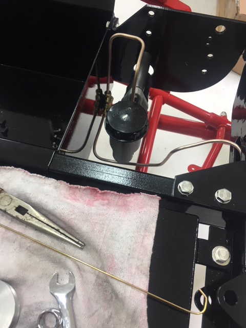
I used the parking brake pulleys that Steam Traction World sent in this kit as a tool to radius bend the brake tubing. If you are not careful you can kink or pinch the tubing and that would be a disaster.
Above was my first attempt of running the brake line before I realized the brass "T" had to be mounted farther forward. 
Re-working my bends. 
And final pathway.


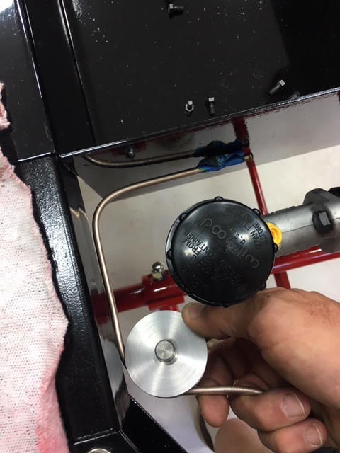
Next was to mount the brake line from the brass "T" forward to the bulkhead fitting.


As you can see there is quite a bit of distance to make up. Luckily, Steam Traction World provided an even smaller parking brake pulley that I could use to reshape this short piece of tubing.

I basically re-radius the bends a little more into an "S" shape to get everything to line up. 

Then the brake line that mounts to the front - tracing the front axle. I pre-assembled the two tubes and one brass "T" loosely before mounting it.
And then mounted the two outboard bulkhead fittings and assembled everything.


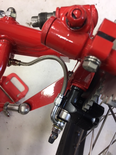
Next was to mount the brake line from the middle brass 'T" to the steering column.

This is a slight problem. The brake line is not making the distance. So a little adjustment to the brake line bends and a little adjustment to the location of the steering tube solved this issue.
As you can see above I had to loosen the steering tube clamps and gently tap the column down with my plastic hammer. You can see the miss-match of the clamp. I had to gently raise that half  (right side) of the clamp - trying not to bugger up the paint. That's it for the front rigid brake lines.
I began working on the rear brake lines, but ran into an issue with the short right side brake pipe. The mounting of the Brass "T" to the rear axle where Steam Traction World drilled and tapped an M6 appears to be just off a little OR the short pipe is just a bit short -- about 7 mm. Ho Humm....

I sent Steve an email, but I believe the solution is for me to move the brass "T" over by drilling and tapping a new M6 hole. The brake line on the other side of the brass "T" is flexible enough to make up this distance. This modification and running the flexible lines will be covered in my next post. 
*** Update: Steve of Steam Traction World is going to send me a longer brake pipe. He didn't want me to drill and tap a new hole.

Popular Posts