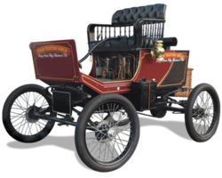
The 1899 Locomobile Steam Car Replica, known as the Lykamobile is a full scale live steam automobile manufactured in 24 kits. This kit is available from a company called "Steam Traction World" located in Daventry, United Kingdom. Each kit is to be manufactured and sent once a month for 24 months. However for cost considerations I have chosen to have my kits batched and dispatched in larger crates to the United States (Topsail Beach, NC).

Specifications:
• Length 7ft 2.6in • Height 5ft 3in • Width 4ft 7.1in • Weight 904 lbs.• Water Tank Capacity 12 Gallons • Fuel Tank Capacity 7.3 Gallons

Construction:

CHASSIS Tubular steel fabrication, combination weld, bolted and silver solder.
STEERING “Ackerman” design tiller steering.
DIFFERENTIAL & DRIVE Spur gear differential similar to the original Locomobile, drive shaft and bearings.
WHEELS & TYRES Single tube pneumatic, treaded.
BREAKING SYSTEM Disc brake system.
ENGINE 21/4" diameter, 3" stroke modified “Hackworth” valve gear.
WATER FEED Twin mechanical pump.
BURNER Fuelled by diesel.
BOILER Multi Fire Tube, fully constructed and complete with necessary paperwork and inspected by notified body.
BODYWORK & SEATS Wooden with steel frame, seating capacity of 2 persons, with turned decorative spindles with leather style upholstery.
Gears: forward and reverse.
Assemble with hand-tools only
Step-by-step instructions
Technical service and help-line backup
Designed on ‘Solidworks’ CAD
Manufactured on modern CNC machines for build accuracy and high quality


Wednesday, March 21, 2018

Front Headlamp Mount Part 1

While waiting for Kits 9 & 10 to arrive, and the fact that even though it is the first "real" day of spring and it is still colder than a "you know what", and I can't get in the garden yet to start the plantings of my summer vegetable garden, I started on figuring out how to mount my Phare-Majestic headlamp.
I have been scouring the eBay website daily looking for brass auto headlamp mounting forks. My lamp has a center distance of about 8 inches between the mounting holes, most Brass Model T Ford headlamp brackets are around 6.5 inches between center. I didn't think I could re-work the Model T fork mounts, but I finally saw a mounting fork for an unknown brass automobile on eBay for $40. I made an offer for $20 plus shipping (carriage) and it was accepted.
Its made of steel and had been chrome plated, but most of the finish was flaking off. I sand blasted it to clean it up. The center distance between the forks was about 10.5 inches. I figured for $20 it was a deal. It gets me really close to what I think I need, but with modifications. First after figuring out how much I needed to shorten the forks, I manually hacked sawed off the forks.
After hacksawing once more to remove the required amount of metal (one side more than the other due to a slight offset of the main center piece), I test fitted the pieces by holding everything together by hand.
(Just look how good I am with a hacksaw -- haha not really, I had to make final grindings on my grinding wheel to get the pieces to line up that way. I made sure I had enough material to do some final fitting from the hacksawing).

Next I center punched by eye the main piece and fork and drilled an 1/8 inch hole for an 1/8 inch roll pin. The roll pin will help to keep things together for final welding or brazing.


The final test assembly with the forks 90 degrees to the original fork configuration.
And another picture showing the pieces that I removed.
Further along the Lykamobile build, I will finalize all of this and probably braze this all together, smooth out the connections points and paint it black. I envision drilling and tapping a rather large mounting hole in the end and mount it to the front cross member of the frame, but that could change too. I will cover this later in another post at that time. (Part 2 here)

And one last thought, you can see in some of the pictures a blue wire, I have electrified the lamp with a halogen bulb rig that I purchased from Restorations Supply Co. Item # ELE318. Follow this link: Acetylene Burner Post Mounted Halogen Lamps to see this item. It simply mounts to the Acetylene post in the lamp and I threaded the wire through one of the vent holes. I will tidy it up on final assembly on the Lykamobile.


Saturday, March 10, 2018

Stewart #26 Speedometer Swivel Drive Mount

I have determined that I can make a simple bracket to mount the Stewart Speedometer Swivel Drive onto the right spindle axle. I mocked up the bracket with a piece of wood to verify my thoughts, making sure that I would have clearance from the M16 Acorn Nut that holds the king pin for the spindle axle. (I didn't take any pictures of the mockup -- it was rather ugly made from a paint stirrer wooden stick). Below I have clamped the bracket to the spindle axle so that I could transfer the locations of the mounting holes/slots. At the end of this posting I have provided a link to the drawing of the bracket that I had made at a local machine shop for those interested.
I used a punch to make a dimple in the steel spindle axle and then drilled a 1/8 inch hole just shy of the depth or thickness of the spindle. I didn't want a through hole. I then chased this hole with a 5.0mm diameter drill bit for tapping a M6(1.0) thread.
Once I had one hole tapped, I again mounted my swivel bracket with a 6mm bolt and transferred the location of the second slot (my clamp was in the way to transfer both slots at once) and repeated my drilling procedure and tapped the second M6(1.0) thread. I always get nervous tapping a blind hole in particular. You don't want to snap off a tap and then figure our how to remove it. I took my time making sure I cleared out the chips as I went along hopefully preventing the tap from binding up and breaking. And as you can see the two tapped holes below were completed without incident.
Obviously you have to mount the Stewart Swivel Bracket onto the Swivel Drive first, then place the drive gear onto the shaft and then feed the cotter pin into the drive gear slot through the cotter pin hole. "Back in the day" this was all they used to fix the drive gear to the swivel drive -- not something I would think to do today, but it works.


Finally everything mounted and aligned.


And a video clip of the gears doing their thing. The rubbing sound you may hear is from the disc brake pad dragging a little on the disc.

In a future post I will show the details of making the drive cable that goes from the Swivel Drive to the Stewart #26 speedometer that will be mounted on the dash or floor board. That won't happen for a while.

Wednesday, March 7, 2018

Lyka Kit #7 Part 3 Parking Brake Final Assembly

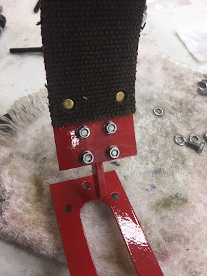
While going over my posts, I realized that I had not posted final assembly of the parking brake. The first step was to mount the painted Parking Brake Lug to the painted Parking Brake Band that I had previously riveted and glued on the brake lining.
I replaced the supplied hardware with stainless steel M5 bolts, nuts and washers. I also added some medium strength thread lock to each bolt to secure them. 
Next you have to open up the brake band enough to slip the band over the differential. The brake band was springy enough to allow this without deforming the band or paint. Three stainless steel M6 bolts, nuts and washers were used to secure the band to the frame cross member. Again I used medium thread locker to secure everything.


Some Lyka builders have stated that they had to bend the brake band to clear the M5 hex bolts. I can see where this might be necessary as viewed from the side (below image).
But at the moment I'm going to wait and see how everything lines up once additional components are installed from future kits.

Popular Posts