The 1899 Locomobile Steam Car Replica, known as the Lykamobile is a full scale live steam automobile manufactured in 24 kits. This kit is available from a company called "Steam Traction World" located in Daventry, United Kingdom. Each kit is to be manufactured and sent once a month for 24 months. However for cost considerations I have chosen to have my kits batched and dispatched in larger crates to the United States (Topsail Beach, NC).

Specifications:
• Length 7ft 2.6in • Height 5ft 3in • Width 4ft 7.1in • Weight 904 lbs.• Water Tank Capacity 12 Gallons • Fuel Tank Capacity 7.3 Gallons

Construction:

CHASSIS Tubular steel fabrication, combination weld, bolted and silver solder.
STEERING “Ackerman” design tiller steering.
DIFFERENTIAL & DRIVE Spur gear differential similar to the original Locomobile, drive shaft and bearings.
WHEELS & TYRES Single tube pneumatic, treaded.
BREAKING SYSTEM Disc brake system.
ENGINE 21/4" diameter, 3" stroke modified “Hackworth” valve gear.
WATER FEED Twin mechanical pump.
BURNER Fuelled by diesel.
BOILER Multi Fire Tube, fully constructed and complete with necessary paperwork and inspected by notified body.
BODYWORK & SEATS Wooden with steel frame, seating capacity of 2 persons, with turned decorative spindles with leather style upholstery.
Gears: forward and reverse.
Assemble with hand-tools only
Step-by-step instructions
Technical service and help-line backup
Designed on ‘Solidworks’ CAD
Manufactured on modern CNC machines for build accuracy and high quality


Thursday, January 30, 2020

Lyka Kit #19 Wiring Part 1

First order of things to do is to drill and mount the control console bracket (LK1902) with the two M4 button head screws and nuts. The instructions didn't provide any dimensional guidance and I may have mounted the bracket a bit low, but I was unsure about clearances. if need be I can adjust its location later.

Once everything is fitted, I will prime and paint the bracket black and remount it for final assembly of the Control Console. But first I need to route the wiring harness loom through the chassis. I took a welding rod that is fairly rigid and stiff to help guide the wires through the chassis. First I loop the two wires for the left side chassis (wires for the inverter on the burner).
Then I feed the welding rod into the left chassis opening and push it through to the other side.

Now I can grab the welding rod and pull the wires through the chassis.
I repeat this process for the right chassis wiring loom.
Look closely below for the copper colored welding rod poking out of the right frame access hole. 
And now I pull the welding rod further out to feed the wires through the right chassis frame. 
I fed the loom through the same grommet that I placed to help isolate the brake line/pipe from rubbing against the frame.


I tried to follow Steam Traction World's instructions for installing the batteries, but I discovered that because of the type of battery I used (due to the fact that in the USA we cannot source the recommended Hankook brand battery), my terminals were opposite and therefore the wiring to the battery terminals was too short. No worries I found away around this as shown below.
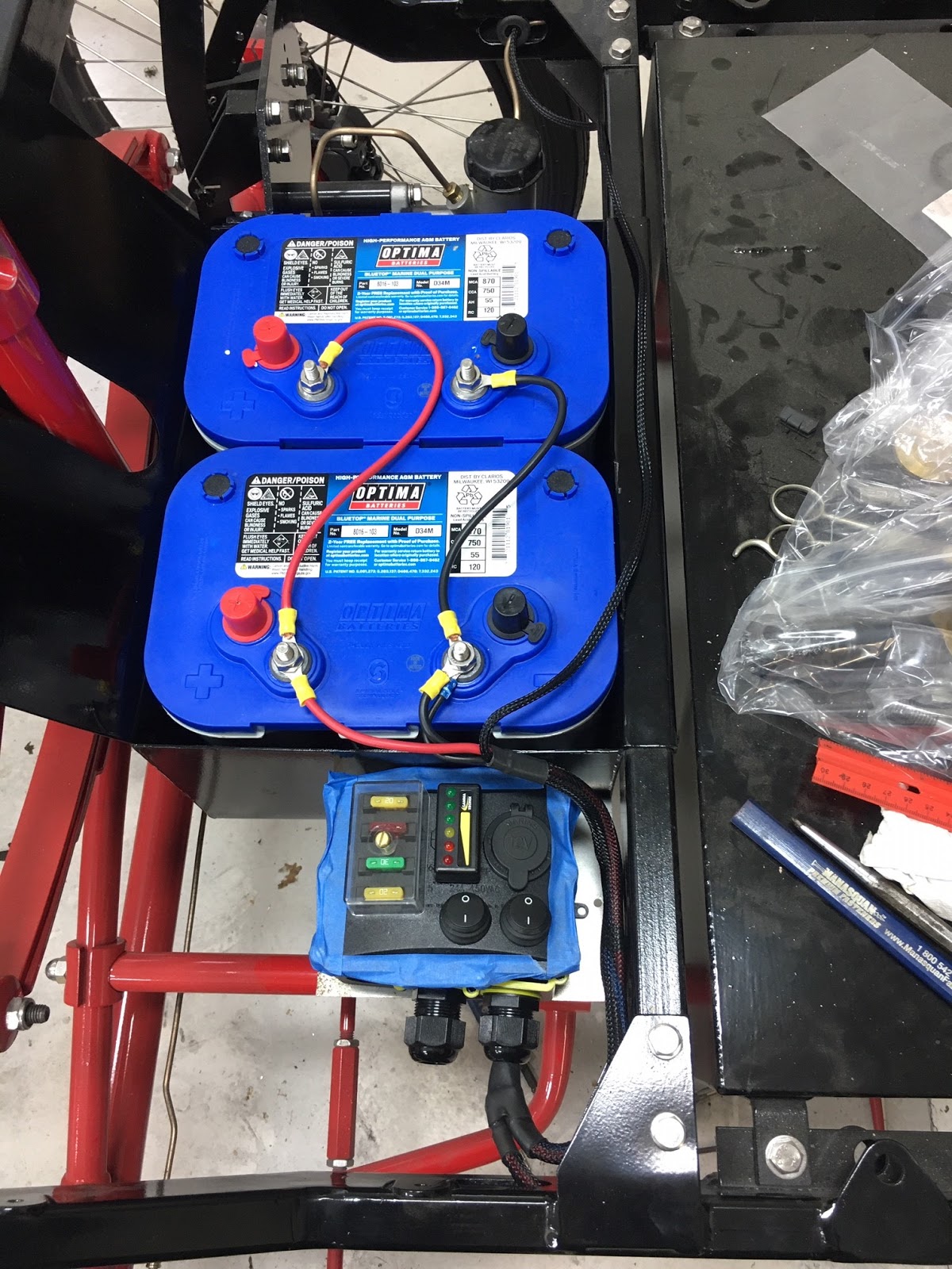
Notice the blue painter's tape around the Control Console. I unscrewed the lid to look inside for future reference for when I run additional wires for the headlamps and brake lights. Steam Traction World only provides a terminal inside the Console Control Box for those builders that want to add lighting. The blue tape is to keep the screws from falling out -- as they did a couple times until I got smart about it!
Below is a close up of the wiring loom going into the left frame member. I purchased a rubber grommet to help isolate the loom from the chassis. I did the same for the brake tube/pipe on the right chassis frame member and fed the wire through that grommet too.
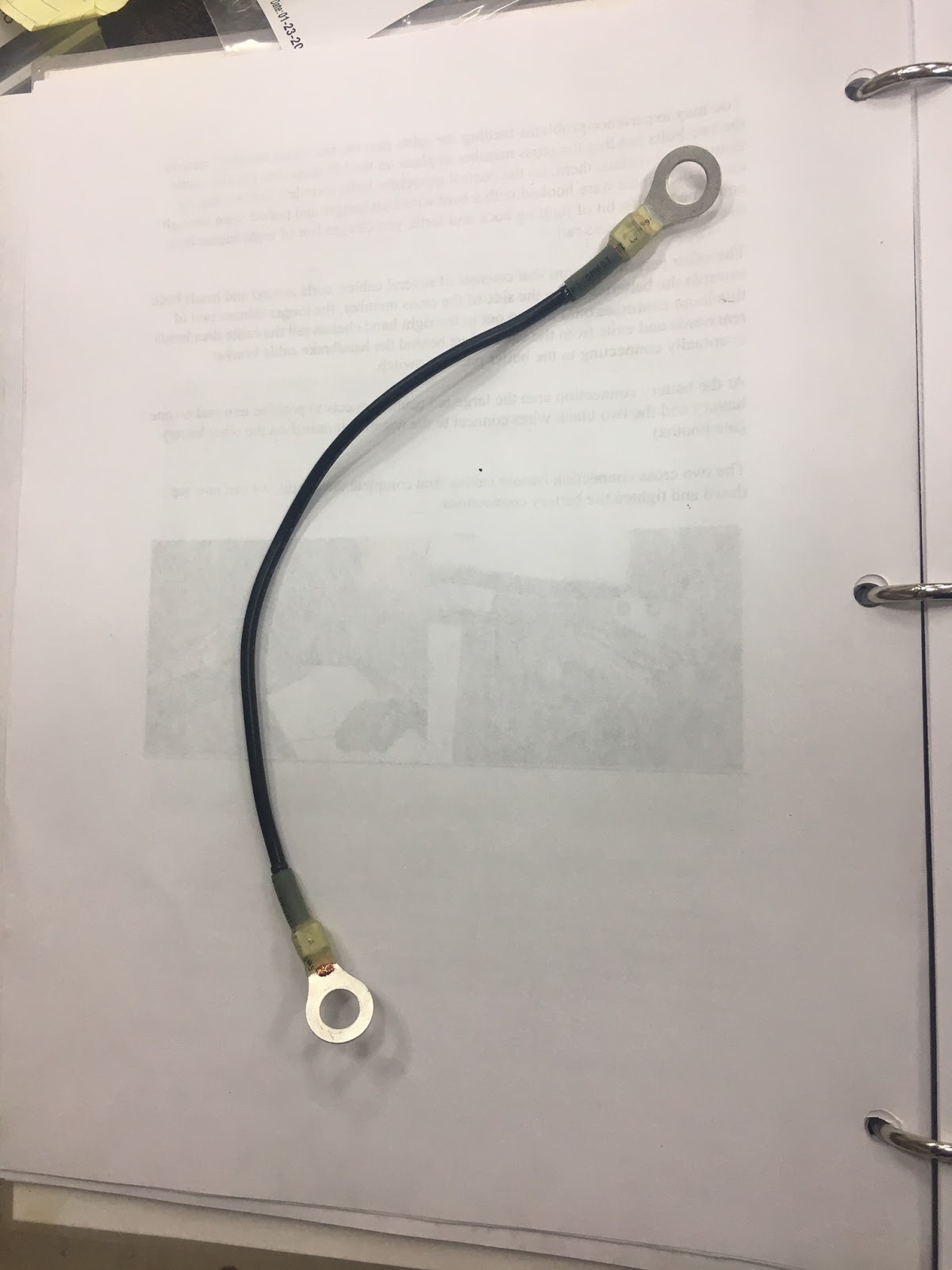
I fashioned a grounding strap for the frame. This will be necessary for the lighting that I will be installing at a later time. It is a 12ga copper strand wire with two 5/16 inch diameter eyelets crimped on each end.
Final layout (I believe) with the grounding strap fitted to the battery and frame. (the positive terminal wire from the loom won't be installed and is taped off for the time being for safety reasons).

The next picture shows the clearances left in the battery box. I may place a rubber strip between the battery and the box just to keep the batteries from bouncing around. To be determined later. But as you can see these Optima D34M batteries fit really nicely in the battery box. My only concern is if the floor board will interfere with the terminals. But I believe it will miss by a millimeter of two, and as they say "a miss is as good as a mile".
I have ordered wiring for the brakes and lights which will be covered in Part 2 for Kit 19 at a later posting.

Thursday, January 9, 2020

Battery Update

I have been in contact with a fellow builder concerning the battery. He recommended to take a look at the Optima spiral wound type of marine battery commonly referred to as the "Blue Top".
Background information from the previous post:
There are several options to choose from:
Target Size:   242mm x 174mm x 190mm (L x W x H Hankook XV65 Battery)
Group 47:      246mm x 175mm x 190mm
Group 90:      246mm x 175mm x 175mm
Group 96R:    242mm x 173mm x 175mm
Group 97R:    252mm x 175mm x 190mm
My battery box measures: 255mm x 352mm x 158mm. Two batteries are needed and must fit in the battery box.
The Optima Battery D34M is best suited for the dimensional constraints of the battery box. Its dimensions are:
D34M:    255mm x 175mm x 201mm + or - 1mm.
I went ahead and purchased one battery for trial purposes. I have a use for the battery if it turns out not to be a good fit. But as you will see from the below images it is a pretty good fit.


The side to side fit is pretty good. The battery actually appears to be slightly tapered with the blue top the largest outside dimension. This is okay because the battery sits a little profile to the battery box. Also my previous concern about the hex head screws are a non issue because the construction of the battery with its cylindrical shape provides the necessary clearance to avoid the hex heads.  My only concern is the height of the battery, however from a previous builder of the Series 1 Lykamobile he was able to get everything to fit under the floor boards using an identical battery. I believe it will be close, but with a little finagle (technical term) it should work out. Below is the battery label. There are two types on Optima style batteries in this blue top size '34'. I got the battery that is for deep cycle use vs. a starting battery.
Just a little warning, these batteries are significantly more expensive than the regular AGM Group 47 batteries, but they supposedly have a much greater tolerance for vibration.

Saturday, January 4, 2020

Lyka Kits 18-19 & Partial Kit 24

Monday December 30th I received 2 1/2 kits that I will soon be working on. These kits include the Cladding, Burner Tray, Wiring Control Unit and all wiring along with a Steering Damper that will be retrofitted to the steering mechanism and finally the wood portions of the seat (the cushions will come separately in the future).
For those builders in United States, the wiring kit calls out a battery that is not available in the USA. Looking at the outside dimensions of that battery (Hankook XV65) it is listed as 242mm long x 174mm wide x 190mm high. There are several options to choose from:


Target Size:   242mm x 174mm x 190mm (L x W x H Hankook Battery)
Group 47:      246mm x 175mm x 190mm
Group 90:      246mm x 175mm x 175mm
Group 96R:    242mm x 173mm x 175mm
Group 97R:    252mm x 175mm x 190mm


My battery box measures: 255mm x 352mm x 158mm and two batteries from the above list are needed and must fit in the battery box.


I'm picking Group 47. Group 97R although is slightly larger (and larger the battery usually means greater the Amp-Hours) - it will be just a little too tight for my comfort to purchase without actually trying the batteries for size. Group 47 on the Length will be 4mm more, but still will have 9mm of space in the battery box. The overall width of two batteries together (175 + 175 = 350mm) is going to be very close with only 2mm of free space versus the 4mm of free space designed for the Hankook battery.


Once I procure the batteries I will update my findings. I also noticed that the hex bolt heads for the brake and clutch "plinth" (bracket) that bolts to the battery box might be a clearance or interference issue. If so I will replace the hex bolts with flat head screws.


Its been a long time since the last kit. Hopefully the remaining 4 1/2 kits will be dispatched quicker!

Popular Posts