July 23rd I was happy to see an email from Steam Traction World that Kit #13 Engine Part 2 was ready to ship and wanted to know if I would like my kit shipped. Of course I said YES! and once again to my surprise FEDEX delivered my kit on July 25! Wow two days from Daventry, England to Surf City, NC.
Kit 13 consists of the Pistons, Water Pumps and Connecting Rods - about 45 Lbs. of metal.
Steam Traction World instructions cautioned to first test the fit of the piston rod with the crosshead due to the dissimilar materials. Stainless steel and cast iron sometimes will gall - meaning they like to grab ahold of each other and not let go! The threaded piston rod wanted to grab the cast iron crosshead some. I decided to chase the threaded hole with an M12 tap and this cleaned up the thread just enough to make threading the rod nicely to the crosshead.
Next was to assemble the Cylinder Rear Cover onto the Piston Rod along with the Piston Gland. The Piston Gland threads into the Cylinder Rear Cover. At this time I have not placed any Gland Packing. The Gland Packing acts as a seal to the piston rod.
The Cylinder Rear Cover fits into the Crosshead Supports. The Crosshead Supports are "handed" - meaning there is a right hand and left hand that attaches to the right cylinder or left cylinder.
A little cleanup was needed to allow the parts to fit.
Now with the test fitting of these parts, its time to place the packing gland material into the Rear Cylinder Cover. The gland packing material is wrapped around the piston rod for measuring.
The next step is to mark with a razor blade the lengths.
I attempted to cut the gland packing on the piston rod, but this is tough material. I had to unwind the material and place it straight on a metal plate to cut. I did discover eventually that on one side of the gland packing it was easier to cut. Seems to have a grain of sorts.
I chose to use three strips of the gland packing (I had to remove one strip for clearance issues - this I will explain in the next Post). You have to stuff the material into the Rear Cylinder Cover and push it down until you can catch a thread for the threaded Piston Gland. I used the Piston Gland to push each strip of material by threading the Piston Gland until it bottomed out in the Rear Cylinder Cover. This packed the gland material into the Rear Cylinder Cover.
I used a small Allen Wrench to pack the material below the threaded portion of the Rear Cylinder Cover.
All Assembled ! But notice the amount of exposed thread. This is the amount of gland packing that can be used up over time before having to re-pack the system. The gland packing acts as a seal and wears over time. Periodically you have to synch up the brass Piston Gland to assure a seal.
Next was to fit the Connecting Rods with the Crossheads and assure that all parts function. The first step I took was to see if the Gudgeon Pin would fit into the Crosshead. A little deburring was required, but the fit was excellent.
Now to see if the Connecting Rods will fit into the Crossheads.
They didn't quite fit -- almost. I had to deburr the inside area of the Crossheads and I had to file down the Connecting Rods too. Basically it looks like I filed away most of the machining marks smooth before it fit nicely. Once the Connecting Rods would slide in, I pressed the bronze bushings into the Connecting Rods with my vise.
The bonze bushing protruded out of the Connecting Rod some (Steam Traction World said this would happen), so these had to be filed away too. I felt it was easier to first get the Connecting Rods to slide into the Crossheads and then press the bronze bushings in and then file the bronze flush with the steel connecting rod.
And it all fits !
Steam Traction World recommended that we grind a few flats on the Gudgeon Pin to allow the set screws (grub screws) a place to rest. The Gudgeon Pins are very hard. I used a little Dremel tool to make my dimples/flats.
At this time I will disassemble the parts and paint the Crosshead Supports and a few other brackets with Gloss Black Engine High Temperature Paint.
Next was the assembly of the brass Water Pump. First you must place the 10mm Balls into the brass pump housing. (sorry about the grungy fingers!!)
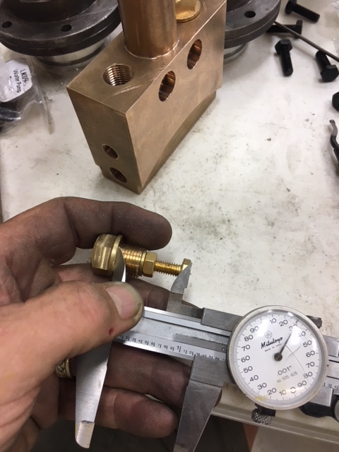
Then assembled the brass hex bolts to the brass fittings. These hex bolts limit the travel of the stainless steel ball.
Steam Traction World suggests that the steel ball should only be allowed to move 1.5 mm. So I took a measurement of the depth to the steel ball and then subtracted the 1.5 mm to set the brass hex bolt length.
And then insert the Pump Rod, Bronze Bushing and Water Pump Gland (without Gland Packing for now)
You will notice I put the Pump Rod upside down. The flange on the pump rod goes up, not into the pump.
And the correct assembly !
Now its time to pack the gland material for the Water Pump. The process is very similar to the piston rod as previously illustrated. Below are the images for the Water Pump. Again I chose to use three strips of gland material.
Below shows the bronze bushing. The distance between the flange and the brass threaded portion of the water pump shows how much gland material there is. As mentioned before over time this gland material wears and you again synch up the fitting to recompress the gland to make a good seal.
Repeat of the assembled image below for clarity.
Steam Traction World sent a modification that needed to be done to mount the Water Pumps to the Main Support Tube. The Water Pump requires two M8 Socket Head Cap Screws and these holes need to be drilled and tapped. They provided a steel template to guide the drilling of the Main Support Tube. Below you see where the steel template has been temporarily mounted. (Thanks to Greg for sharing his pump assembly via email; I realized I have mounted the template upside down - this I will correct soon and re-tap my holes) The two holes are used to guide the drill bit to the proper location. First you drill a 5.0 mm hole and then take the template off and open this hole up to a 6.8 mm hole. Then use an M8(1.25) tap to thread the hole. This operation is done on both sides of the Main Support Tube.

Once the holes were tapped I attempted to mount the brass water pumps for fit. Drilling and tapping M8 holes by hand is not an exact science. Of course my drilling wandered off a bit. So I had to open up the clearance hole just a little and also elongate the counter bore in the Water Pump to allow me to align the Water Pump parallel with the Main Support Tube. I was only off a bit, but as you can see below the pump is nicely aligned now.
Lyka Kit #13 Engine Part 2b will be posted next showing the final assembly of the parts after paint. Unfortunately our kits did not ship with the piston rings and a "true final" assembly can't be done until we receive the piston rings.