Steam Traction World is supposed to be sending us Steaming Instructions that have not been written up yet, so being a little impatient I decided to hookup my air compressor to the inlet feed pipe which is located on the top of the boiler. This is a 3/8" pipe thread that will eventually be plugged once the first initial fill of water is done. I set the air pressure to 100 psi. Below is a video of the engine running in reverse. The engine uses a modified Hackworth Valve Gear and per the design the engine actually runs smoother in reverse. I suspect the engine has more power in forward though. I used some Chevron Meropa 680 gear oil for the steam oil. Still waiting to hear from Steam Traction World for a specification on the proper oil to use.
Very exciting to see the engine run at last !!
Now that I have the system pressurized I can start to chase down any leaks. Plain old dish washing soap and water is applied to all the fittings. I notice a few leaks here and there. One leak is at the interface between the two components for the throttle regulator valve.
I tried to use the Steam Seal Joint compound and this did not work. The threads are straight threads. I had to resort to High Temperature Silicone Gasket Maker - this did work.
I had a leak at the pressure gauge and this was solved with one rotation of the pressure gauge. Also I can hear inside the boiler at the inlet feed pipe a small leak. I had problems with this pipe fitting/thread and I suspect that the pipe thread was over cut and the taper was a bit too small. I will monitor this once the boiler is up to temperature to see if the expansion of the boiler seals the leak. It is a small leak and possibly won't be an issue with steam. I have also notice small leaks around the interface of the valve chest bolted to the cylinder blocks and again I will monitor this. It would be a big job disassembling to apply another amount of steam sealant there. All of the leaks so far have been very minor.
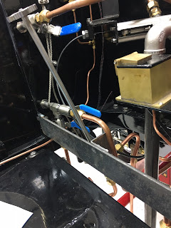
Next I decided that I was not too thrilled with the way Steam Traction World mounted the cylinder blow-off valve. This valve is mounted to the backside of the main floor board with 4 lag bolts. Any time that you want or need to take the floor board out would necessitate disassembly of the 4 lag bolts from underneath the chassis. My solution was to make a bracket and mount the valve to the frame. Below are the images for this.
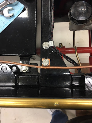
The cross bar bracket is bolted to the frame and is flush with the frame. I used flat head countersink screws. And finally for this update, the last item was to secure the 1/4 inch copper tubing that goes to the pressure gauge to the frame. A simple strap was made and I used a frame cross-member bolt to secure it. I felt that this was necessary to prevent a rattle. No doubt I probably wouldn't be able to hear it, but I eliminated it anyway.
And one last detail: I hooked up the chain and decided that I needed to get an offset link (half link). The chain is just a tad too long (by a half link), so I will have to take a full link off the chain and then use the half link to reduce the slack. Without this, the chain would be slapping around beating "things" up.
Trials and Tribulations Part 2 will be final details for the floor boards.


No comments:
Post a Comment