The 1899 Locomobile Steam Car Replica, known as the Lykamobile is a full scale live steam automobile manufactured in 24 kits. This kit is available from a company called "Steam Traction World" located in Daventry, United Kingdom. Each kit is to be manufactured and sent once a month for 24 months. However for cost considerations I have chosen to have my kits batched and dispatched in larger crates to the United States (Topsail Beach, NC).

Specifications:
• Length 7ft 2.6in • Height 5ft 3in • Width 4ft 7.1in • Weight 904 lbs.• Water Tank Capacity 12 Gallons • Fuel Tank Capacity 7.3 Gallons

Construction:

CHASSIS Tubular steel fabrication, combination weld, bolted and silver solder.
STEERING “Ackerman” design tiller steering.
DIFFERENTIAL & DRIVE Spur gear differential similar to the original Locomobile, drive shaft and bearings.
WHEELS & TYRES Single tube pneumatic, treaded.
BREAKING SYSTEM Disc brake system.
ENGINE 21/4" diameter, 3" stroke modified “Hackworth” valve gear.
WATER FEED Twin mechanical pump.
BURNER Fuelled by diesel.
BOILER Multi Fire Tube, fully constructed and complete with necessary paperwork and inspected by notified body.
BODYWORK & SEATS Wooden with steel frame, seating capacity of 2 persons, with turned decorative spindles with leather style upholstery.
Gears: forward and reverse.
Assemble with hand-tools only
Step-by-step instructions
Technical service and help-line backup
Designed on ‘Solidworks’ CAD
Manufactured on modern CNC machines for build accuracy and high quality


Thursday, June 18, 2020

Lyka Kit #23 Bodywork Side Panels

Well I was hoping to not drill any more holes into my finished side panels, but I decided that to make a secure attachment of the forward sections would be best. Listening to Jim Trotta (Series 1 Lykamobile) on a YouTube video he posted, he suggested that over time bolting the side panels would crack the paint due to the bolt compressing the wood area. His solution was to press and flare some copper tubing in the side panels that the bolt would go through and provide the necessary structure to securely bolt the side panels without compressing the wood. That gave me inspiration to think about a different way to accomplish most of what Jim did. I settled on Brass Binding Barrel Bolts found at McMaster Carr.
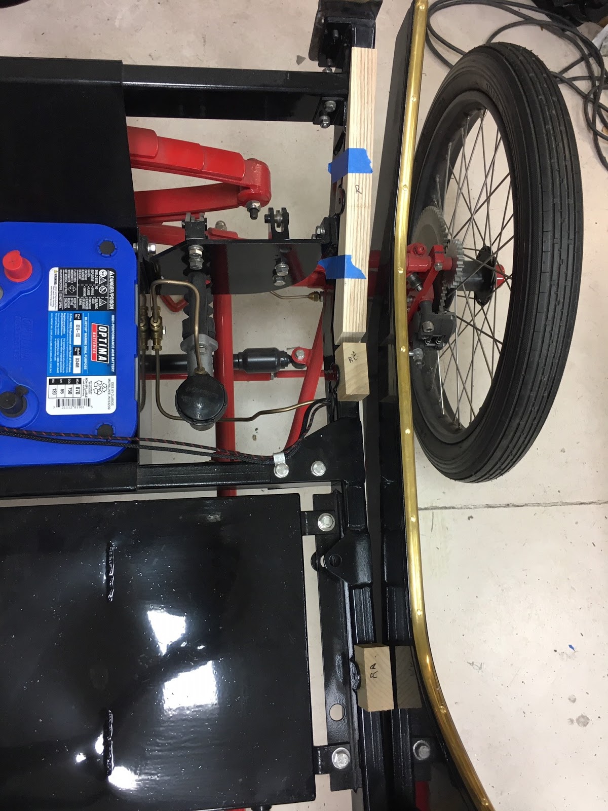
The length would need to be cut to about 34 mm to provide the correct fit through the side panel and wood blocks etc. But first I layout the blocks and position them. You need to be careful with the angular wooden blocks. I noticed that the side frame welds protruded some preventing the blocks to lay flat. A little grinding and touch-up paint solved that problem.


Positioning of the angular blocks required a little sanding of the block on the interface of the wood to the metal frame. I kept testing the floor boards until I was satisfied with the locations of the angular blocks. The floor board lays on the angular piece without and wobble or gaps side to side.
Now it is time to drill some pilot holes into the wooden blocks. I mark the blocks and then use a small drill bit first.

Then I place these blocks back into position and drill a pilot hole by using the drilled block hole as a guide from the back side of the panel.


Now I drill the proper size hole (slide fit) for the Binding Barrel from the front side of the panel.
I will later paint the blocks and the interiors of the holes for weatherproofing. Now after cutting the Binding Barrels to 34 mm, they are inserted and using a brass pan head screw and washer tighten everything up. The Binding barrel slightly compresses the side panel and bottoms out against the metal frame flange. I did polish the heads of the Binding Bolts a bit, my wife likes the brass, I may paint them black to hide them a bit. I'll decide that later after a while.


The final images all done.

No comments:

Post a Comment

Popular Posts