The 1899 Locomobile Steam Car Replica, known as the Lykamobile is a full scale live steam automobile manufactured in 24 kits. This kit is available from a company called "Steam Traction World" located in Daventry, United Kingdom. Each kit is to be manufactured and sent once a month for 24 months. However for cost considerations I have chosen to have my kits batched and dispatched in larger crates to the United States (Topsail Beach, NC).

Specifications:
• Length 7ft 2.6in • Height 5ft 3in • Width 4ft 7.1in • Weight 904 lbs.• Water Tank Capacity 12 Gallons • Fuel Tank Capacity 7.3 Gallons

Construction:

• CHASSIS Tubular steel fabrication, combination weld, bolted and silver solder.
• STEERING “Ackerman” design tiller steering.
• DIFFERENTIAL & DRIVE Spur gear differential similar to the original Locomobile, drive shaft and bearings.
• WHEELS & TYRES Single tube pneumatic, treaded.
• BREAKING SYSTEM Disc brake system.
• ENGINE 21/4" diameter, 3" stroke modified “Hackworth” valve gear.
• WATER FEED Twin mechanical pump.
• BURNER Fuelled by diesel.
• BOILER Multi Fire Tube, fully constructed and complete with necessary paperwork and inspected by notified body.
• BODYWORK & SEATS Wooden with steel frame, seating capacity of 2 persons, with turned decorative spindles with leather style upholstery.
• Gears: forward and reverse.
• Assemble with hand-tools only
• Step-by-step instructions
• Technical service and help-line backup
• Designed on ‘Solidworks’ CAD
• Manufactured on modern CNC machines for build accuracy and high quality


Monday, May 17, 2021

Having Fun !

Last part of March, 2021 fellow Steam Locomobile Replicar builder Jim Trotta and his lovely wife Terri stopped by on his way home from Florida to New Jersey. Jim built one of the Series 1 Likamobiles and has quite a depth of knowledge on these steam cars. First off he says Likamobile and I say Lykamobile :) but it is all the same fun!

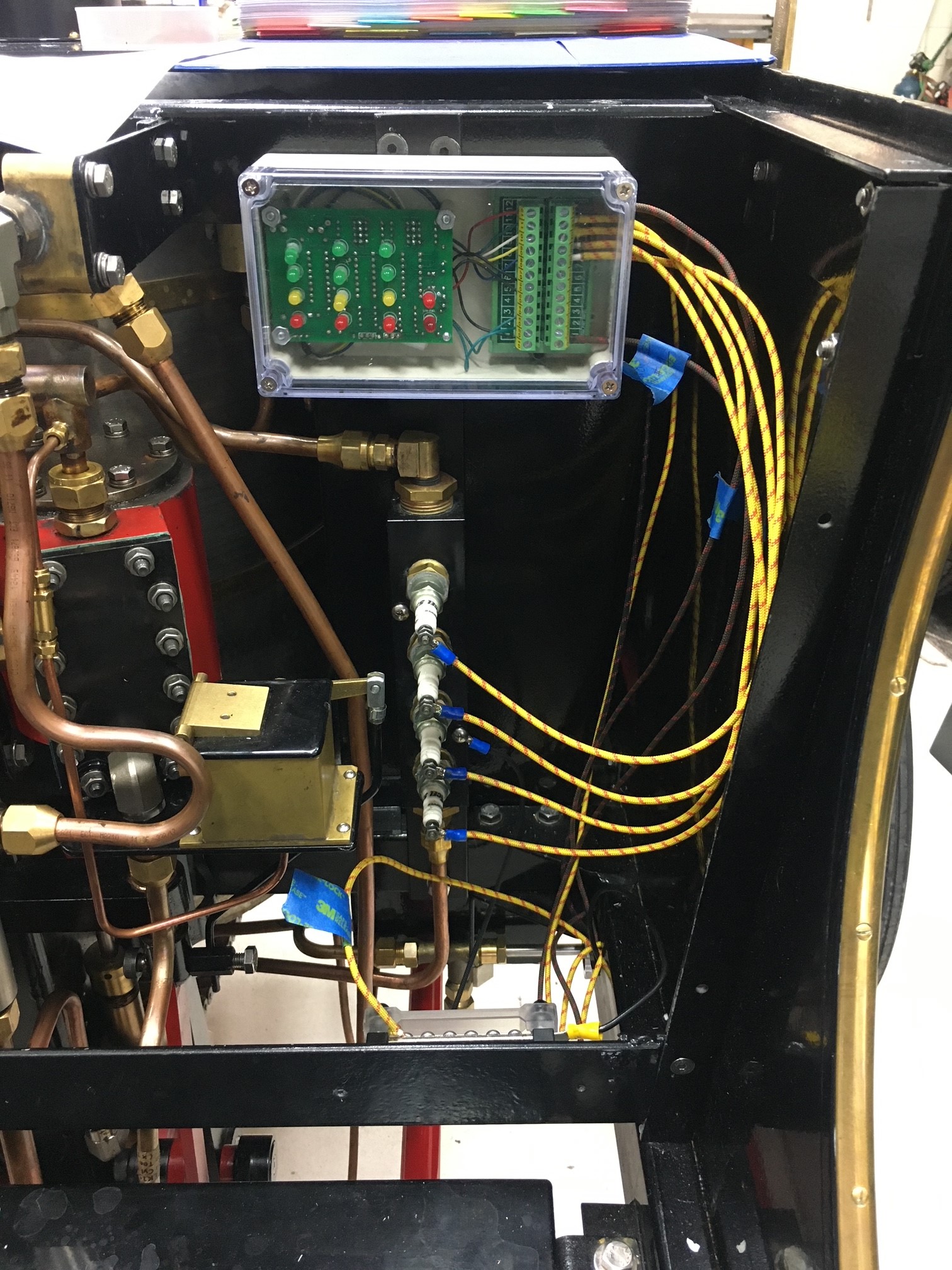
Jim came up with a circuit board that replaced the Series 1 circuitry. He made improvements and added a few additional areas to monitor. Our Series 2 Lykamobile removed all of the electronics and relies on manual and visual observations of the boiler. I accidentally overheated my boiler and caused me to re-seat every copper tube (288 of them) on both ends. There is an earlier post detailing this so I won't go into details. Anyway here is a picture of Jim's circuit board that I have mounted under the seat.

In a previous post I detailed using a different circuit board that would be an emergency cut-off of the boiler if the water level goes too low. The following picture shows the manifold with 4 spark plugs as the sensors. I reused this manifold with Jim's circuit board.
Jim's circuit board replaced the original Series 1 electronics and was mounted in a brass console on the passenger side floor board area. This would have been a bit more work, I took the easy way out and mounted the board sort of out of the way. The features that I was most keen to use that Jim's circuit board would allow is to first have a low water cut-off and secondly allow for automatic filling of the boiler via a solenoid actuated valve. This solenoid valve cuts off the bypass water and diverts the water to fill the boiler. The way Jim's board works is that a valve is actuated when the top LED (green one third row from the left) goes off. The valve closes and fills the boiler until the green LED turns back on.

The first row of lights is a battery voltage monitor (which we do have next to our battery), the second row of lights is to monitor the water tank level (I don't use this section).

The two red LED's on the right with the top one indicates when the solenoid valve is actuated and the bottom red LED blinks when your fuel tank is low (I have mounted a stainless steel float in my diesel tank - I check it once when steaming up to see if the LED is blinking). I have mounted an LED light on the dash board to turn on when the solenoid bypass valve has been actuated and it is pretty bright so that I can get some reassurance that the bypass solenoid valve is working. Below is a video of the LED showing when the top spark plug is disconnected the valve will be actuated and water diverts into the boiler to fill it.
Jim helped me figure out all of the connection details for the circuit board and helped troubleshoot my work - eventually we got it all to work.

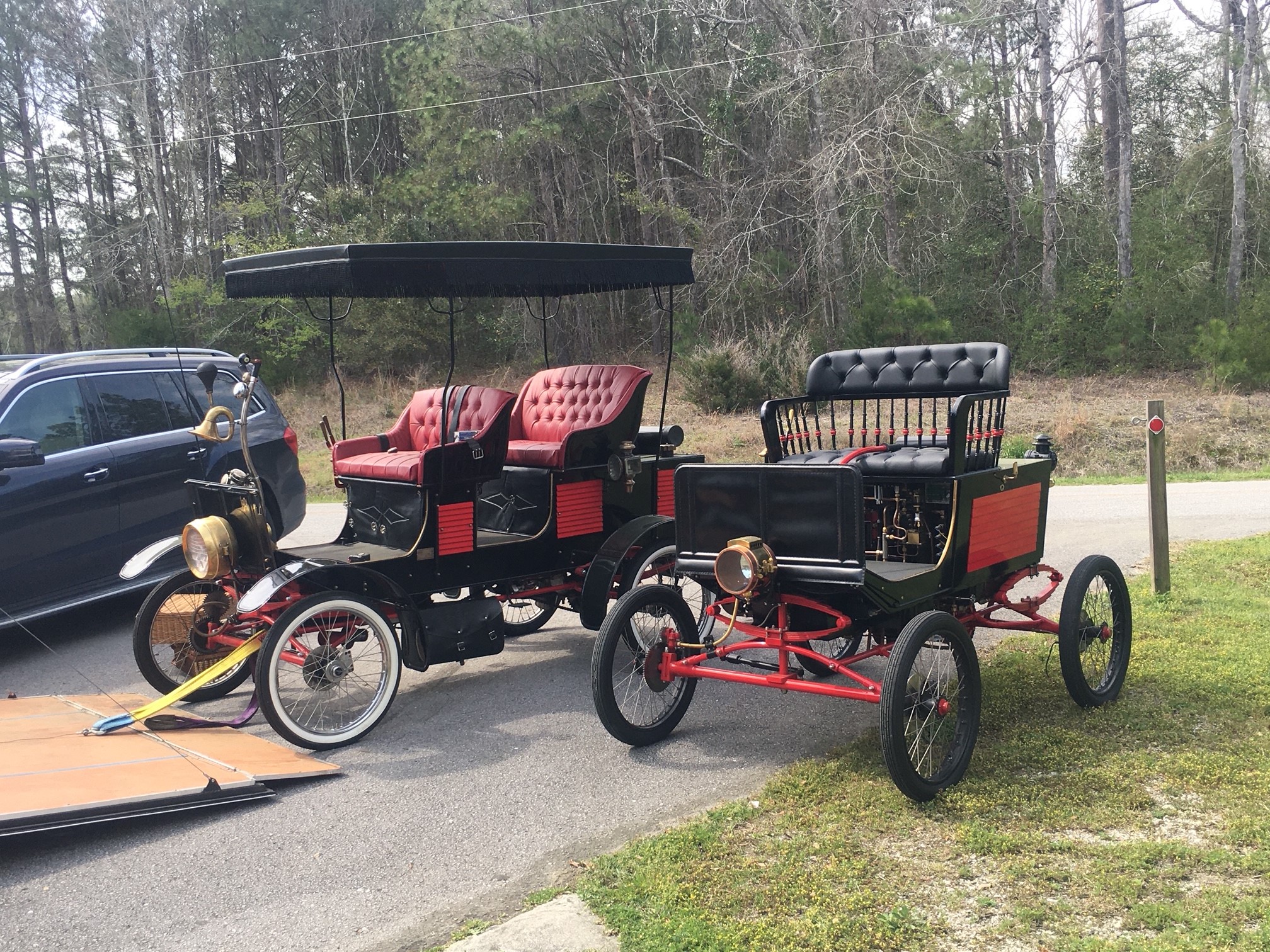
Once we got everything working, Jim took out his Likamobile Surrey that he has built and we went over all of the modifications and improvements he has made over the years. Jim's Likamobile started out as a two seater, but unfortunately while he was trailering the car, someone rear ended him and totaled his Likamobile. Not being deterred, Jim decided to take this as an opportunity to rebuild bigger and better! Below are a few pictures of us showing off our steam cars and finally two videos of my Lykamobile steaming away and coming back.


Jim's car was in-between repairs so he wasn't able to fire it up. I'm hoping that this fall on his way down to Florida we can fire up both for a little spin. Below are two videos of my Lykamobile.
Happy Steaming!!!

Saturday, March 20, 2021

Modification of the "Modified Hackworth Valving System"

Several months ago I mentioned a possible modification to the already Modified Hackworth Valving System that Steam Traction World designed into the Lykamobile. I had a conversation with Ian (of Steam Traction World) about the best practices for timing the engine. In that conversation I mentioned that with the Series 1 and/or the Model Works version of the Lykamobile, that it had been recommended to adjust the position of the reverser about 3/4 of an inch further rearward.

From Model Works Series 1 Memories and Dreams Blog: "The timing of the valves has changed from the original instructions; the original set up gave the car a lot of power in reverse and mediocre power in forward."

Below are a few pictures from his blog showing how it was recommended to time the reverser.

You can see from the above photo the linkages for the valves. The inner linkage is mostly vertical. Also note that the Series 1 connecting rod to the right at an angle passing the brass block is an actual rod welded into an assembly that houses the bearing. This will be an important detail later. The next two photos shows where the linkages were and where they recommended how to fix the timing.

Original Location.
Recommended Location.
For the Series 2 Lykamobile, modifications to the linkages are required to adjust the linkages more rearward. In the Series 2 I believe that the crank counterbalance is a bit larger. Our linkages (adjusted in the vertical position as recommended by Steam Traction World) left no room to move the linkages further towards the crank. The linkages needed to be modified. I discussed this with Ian and he said it was possible that in the future they may provide linkages with a bit of a curvature to allow a better valving set up. So I took it upon myself to try this modification out on my own. Below is one of the linkages where I have ground away material to allow the link to be moved about 1/2 of an inch closer to the engine.
As you can see the link is still very structurally sound. A bit of trial and error was needed to arrive at this curvature. I would place the link back on and see where I needed to grind some more for clearance. This was an iterative exercise. Below is how it looks assembled.

I re-timed the engine valves with the reverser as far rearward to the engine as possible without hitting the counterbalance or brass water pumps.  I then test ran the engine under steam with the rear wheels up in the air so the car was stationary to look things over. I discovered that I had a slight knock and after a while I figured out that the connecting rod was banging ever so slightly on the linkages in two places over the crank cycle. That is because our connecting rod was fabricated out of one piece of flat stock steel vs a rod welded together as in Series 1. This necessitated a little more grinding on the red linkage that is attached to the black linkage and a little grinding on the actual connecting rod. Below are the pictures for the connecting rod. Again this was an iterative exercise until I was satisfied that everything had enough clearance. 
In this next picture you can see where the red linkage was interfering with the crank and where I removed some material from the crank and red link.


I feel that this modification is helping with the forward power with little to no perceivable difference in reverse. I also believe that the Lykamobile has an easier time starting from standstill to forward motion. It is still possible to further this modification a bit more provided there is room on the brass pumps to remove a little of the corner as shown below. However at this time I am satisfied with this modification and plan not to do any additional modifying of the linkages. 

Wednesday, March 10, 2021

Lunkenheimer Type Oiling System

February and the beginning of March 2021 has been a very wet and cold spell which brings a lot of idle time to think about the Lykamobile. This has brought me to wanting to create a oiling system for parts of the steam engine that will need periodic oiling. Now you might say what's the big deal, just squirt some oil here and there and all will be good. That's no fun! (at least for a mechanical engineer). So having seen modifications of similar rigs on the Series 1 Lykamobile, I embarked on adding this "accessory". Below is a reproduction of a Lunkenheimer oiler. This oiler operates by metering a slow drip of oil and is adjustable. It also has a cut-off so that oil can be stopped.

Next I decided to use 1/8 copper tubing and 1/16 NPT fittings - all of which is a bit difficult to find due to its small size. Mostly when you go down to this size it is a specialty for instrumentation etc. First I need to drill and tap the 1/16 npt holes on the engine.
I repeated this on the opposing side of the guide block and also on the second cylinder (4 places). I procured from McMaster-Carr a three port distribution block, made a bracket that is mounted with two of the top cylinder head bolts.
The next few pictures shows the routing of the 1/8 inch tubing. I also routed some tubing to the front bronze bushings that guide the valve stems.

The engine is now back in the Lykamobile ready for some good weather to steam it up. I envision only turning on the oiler as part of the steaming up process and turning it off once underway. 

Thursday, February 25, 2021

Engine Packing Nut Modification

After steaming the car several times, invariably one of the piston stem rods packing nut will vibrate loose and eventually unscrew to where the piston stem rod guide (slider) bangs against the packing nut. This is not good, and makes a rather load knock too. I have tried various things, like aviation sealant that stays semi-fluid to make the threads "sticky" thereby eliminating the unscrewing of the nut, but because this area becomes rather hot, the sealant liquefies and the nut still rotates loose. So inspired by an old Mason Steam Engine that Locomobile use to use, I am adopting their solution to this problem. First the next image shows the packing nut that I'm referencing.
The next image shows how the Mason Steam Engine stopped their packing nuts from loosening from the vibrations of the engine. The image shows the packing nuts for the valve stems, but they also used the same idea on the piston rods too.
So I decided to create a sheet-metal bracket that would provide tension against the packing nut, but first I needed to file away a radius so that the bracket would sit and align better with the packing nut.
I then unscrewed the M6 hex head cap screw above the filed away radius. This will be where I will attach the sheet-metal bracket. I made a cardboard pattern to prototype my bracket and then transferred this to my sheet-metal to make.

I bent the sheet-metal and brazed some welding rod to the bracket that will interface with the packing nut.
(as a note, the 12 3/4 is the number of full turns on the connecting rod slider block that took to unscrew the slider from the piston stem rod- I wanted to make sure that when I reinstalled the slider it was in the same relative position on the piston stem rod) 
Next I used a hack saw, small flat file and small round file to make grooves between each hole on the packing nut. To get to this packing nut I had to first remove the steam engine from the body to allow better access to all of the parts. I disconnected the connecting rod from the slider, then unscrewed the slider to allow the packing nut to be unscrewed from the piston rod. (I'm getting good at removing the engine - this being about the forth time I have done this).
The next few images shows the bracket and packing nut assembled on the engine. I am hopeful that this will eliminate this issue. My only concern is the gauge of sheet-metal I used. I may have to re-make the bracket out of a heavier gauge - I used 22ga.


This modification really should be done for all future Lykamobile Engines. Steam Traction World should design something to prevent this packing nut from unscrewing. My solution may not be the best, but I think something should be designed to stop the packing nut from loosening. Just my 2-cents.

Saturday, February 6, 2021

Water Tank - Boiler - Bypass System

I don't know how many times I have had to trace the plumbing to figure out the water circuit for the filling of the boiler and the bypass valve. The bypass valve when open will provide a piping system that allows the pumps (that are mounted to the engine that pump all the time when the steam engine is running) to "bypass" the filling of the water into the boiler. This is important because the boiler should not be filled to the very top ever. The boiler needs some head space for the steam to be generated and pressurized. This pressurized steam is what is sent to the engine to be expanded to drive the pistons up and down. Below is a hand drawing/sketch of the system with the bypass valve open.

I did not draw in the engine, but the engine drives the two pumps. The pumps will circulate water through the tanks in a loop. When the bypass valve is closed, then the water path changes as indicated in the next sketch.
With the bypass valve closed, the pumps will pump water into the boiler. The pumps are strong enough to lift the check valve ball and fill water into the boiler. You will notice that in the sketches there is a hand pump. This hand pump is used to fill or prime the boiler for the first time or whenever the boiler level is too low to fire up the boiler safely. To use the hand pump the bypass valve must be closed. If you don't close the bypass valve you will just be circulating most if not all of the water to the tank and not be filling the boiler.

Saturday, January 9, 2021

More Shake Downs and Modifications

In my last post I wrote about how on one side of my engine one of the cylinders became loose and was moving up and down with each stroke. At the time I thought I could possibly fix it with the engine in the car ---WRONG! I had to take it out to access all of the bolts to get at the loose flat head screws. I fixed that side and put it all back together. Did another steam up - and LOW AND BEHOLD the other side became loose. What a dummy for me not to go ahead and proactively tighten everything up. Below is a movie of the cylinder moving up and down.

So once again I had to take the engine out, but this time it didn't take me as long -- getting good at taking this car apart! I believe the issue that is causing the flat head screws to become loose is because I painted the bracket without taping off the countersink holes. I believe the paint is degrading and becomes soft and then will ooze out causing a looseness of the fit to occur. Once this happens the screw will continue to loosen up. So next time I won't paint the screw holes (if there is a next time). Below you can see the paint is all chewed up and actually is like powder.
Below I sand blasted all the paint away so now I will have a metal to metal fit.
The engine is all put together again, and this time I took my time to realign the valve bushings/cross bar for a much smoother sliding action too. The following picture shows the cross bar I realigned - the picture is from the first time I aligned the bar.
While I had everything apart, I decided to change my stop light switch from a Hydraulic switch to a simple mechanical switch. I was finding that the hydraulic switch was not always working. I've had enough issues with bleeding the system, that I decided a good old mechanical switch would be most reliable. I found a normally closed switch at our local building supply and fashioned a bracket out of some flat stock steel. Below details what it looks like:

I have done a little modification of the Hackworth Valving System. I have not tested it yet, but if it works out that will be my next posting. Supposedly the modification was suggested during the Series 1 Lykamobile build or possibly the Modelworks build, however our engine design is slightly different from the earlier build, so a modification was necessary on our linkages. The modification is suppose to provide a stronger forward and possibly a bit smoother. It will be a couple of weeks before I can post it. I am going out of town on business.

Popular Posts