The 1899 Locomobile Steam Car Replica, known as the Lykamobile is a full scale live steam automobile manufactured in 24 kits. This kit is available from a company called "Steam Traction World" located in Daventry, United Kingdom. Each kit is to be manufactured and sent once a month for 24 months. However for cost considerations I have chosen to have my kits batched and dispatched in larger crates to the United States (Topsail Beach, NC).

Specifications:
• Length 7ft 2.6in • Height 5ft 3in • Width 4ft 7.1in • Weight 904 lbs.• Water Tank Capacity 12 Gallons • Fuel Tank Capacity 7.3 Gallons

Construction:

CHASSIS Tubular steel fabrication, combination weld, bolted and silver solder.
STEERING “Ackerman” design tiller steering.
DIFFERENTIAL & DRIVE Spur gear differential similar to the original Locomobile, drive shaft and bearings.
WHEELS & TYRES Single tube pneumatic, treaded.
BREAKING SYSTEM Disc brake system.
ENGINE 21/4" diameter, 3" stroke modified “Hackworth” valve gear.
WATER FEED Twin mechanical pump.
BURNER Fuelled by diesel.
BOILER Multi Fire Tube, fully constructed and complete with necessary paperwork and inspected by notified body.
BODYWORK & SEATS Wooden with steel frame, seating capacity of 2 persons, with turned decorative spindles with leather style upholstery.
Gears: forward and reverse.
Assemble with hand-tools only
Step-by-step instructions
Technical service and help-line backup
Designed on ‘Solidworks’ CAD
Manufactured on modern CNC machines for build accuracy and high quality


Monday, June 4, 2018

Lyka Kit #12 Engine Part 1b


After waiting not quite 7 days for the red brake caliper paint to cure, the paint seemed to be tough enough for handling.
I begin by placing the cranks onto the mainframe shaft.

And I quickly realize now what Steam Traction World's instructions meant by "You will need to remove a small amount from the rib of the Bearing Housing so that the Crank Web has a bit of clearance". You can see that the crank is touching the bearing housing and the crank shaft will not rotate. So disassemble and once again utilize my right angle sanding disc to remove some of the material. But first I mark the area of the rib that doesn't need to be cleared with blue tape.


Turns out that I didn't need top mark the rib with blue tape because I decided to just reduce the whole rib for clearance.
Now that both ribs have been modified, I once again assemble the cranks onto the crank shaft.
You can see everything works.
Now on to the steam cylinders. I sent a inquiry to Steam Traction World on whether or not I should paint the steam cylinders. Before I heard back, I had already painted the "non-critical" surfaces with the high temperature red caliper brake paint. Steam Traction World basically told me it was my preference, but they would not recommends it due to the high temperature the cylinders would experience. I did a little research before painting and our Lykamobiles will be operating in the 200 psi (pounds per square inch) range. This equates to about 300° F for saturated steam. The paint should hold up - but time will tell.

Next mount the two backing plates to the cylinders.
I used the bearing grade adhesive to lock the threads. I tried to dimple the flat head screws with a punch, but wasn't too successful because of my setup. I'm going to rely on the adhesive. Next I mounted the cylinders to the mainframe.

And I couldn't resist, I placed the whole assembly temporarily into the Lykamobile (also for safe storage) to see how it all fit.


And just to do a little check on alignment between sprockets, I placed a straight 2x2 wooden stake to eyeball everything. It looks good.
One last item that I'm posting which is unrelated to this kit is that I found a gasket for the fuel tank. Costs about a $1 to $2. Got it from Sanitary Fittings LLC online. Fits perfectly (1 1/2" OD Tube spec).

Thursday, May 31, 2018

Lyka Kit #12 Engine Part 1a

On May 10th, 2018 Steam Traction World dispatched the first kit of three for the steam engine. There were two parcels, one was the mainframe for the engine, and the second was the machine parts for the cranks, cylinders, mounting brackets and hardware. I was excited to see that one of my parcels arrived on May 17th. Pretty darn good!, however looking at the tracking history, I could see that the parcel with all of the various machine parts was stuck in Memphis, TN (FEDEX's main hub). I waited to the 21st to file a missing parcel report. Luckily my package was found and was finally delivered on the 23rd. The box was beat up, a tear in it and some of the hardware was loose. Also most of the machined parts had dings from rattling around in the box. I made a suggestion to Steam Traction World to possibly double box in the future for overseas shipment - especially if it is a heavy box with many parts. The box was more round than rectangular. Anyway - all the parts were present and accounted for - luck me 😊
.
So of course the process is to deburr, prime and paint. I have chosen to paint the mainframe, cast bearing blocks black.
The cranks and cylinders I decided to paint them bright red to add a little pizazz, similar to the chassis. However thinking about the temperature that the steam cylinder would see, a little research indicates that the steam will be around the 300°F mark for a pressure of 200 PSI, this I believe requires a better paint than what I used on the chassis. So off to the local auto parts store to browse the paint section. I found a pretty good match that is used on disc brake calipers that can withstand temperature up to 500°F. The only down side is that this paint has a 7 DAY cure time !! I decided to paint the Cranks with this paint to match the cylinders.
Before painting the steam cylinders, I happened to go on Alan's Steam Car Blog and noticed how Alan was modifying the steam exhaust port. Alan's right about smoothing the transition. As currently machined the exhaust port sees a sharp obstruction. This would cause an unnecessary restriction with turbulence, reducing the flow. Who knows by how much, but design-wise it is common sense to smooth this transition. (By the way, I check all fellow Lyka builder's blogs a lot! I learn so much from their experiences because they are usually ahead in their build). You can just barely see in the next picture how the exit port is occluded. See below:
After a little Dremel tooling with a dremel cutter....
A much smoother transition.
I actually elongated this a bit more. Now the cylinders are ready to be painted with the red disc brake caliper paint....and wait seven days!  In the meantime, I will try to assemble the crank shaft into the main engine frame.
The first task is to see if the chain sprocket will fit into the mainframe.
Whelp, it doesn't. It appears that the weldment bead for the rectangular tubular steel is just barely interfering.


Again using my Dremel and dremel cutter I remove as much as necessary to allow the sprocket clearance to be assembled.

And the placement of the sprocket with the shaft in the mainframe pictured below:

 
Next I need to assemble the bearings into each bearing bracket. This is achieved by using my vise that I have equipped with plastic jaws to gently press the bearing. You never want to press a bearing into a housing by pressing the inner race - only the outer race for a bracket like this one. If you were to press the inner race you would be pressing on the ball bearing balls and indenting them, making a "ding". This would cause premature failure.
Of course if I had an Arbor Press I would use that instead of my vise. Next picture shows the bearing bracket assembled on to the mainframe and sprocket shaft.
At this point I disassemble everything to touch up the paint from grinding away the inside weld in the mainframe and wait the 7 days for the red caliper disc brake paint to cure before attempting any more assembly. That will be covered in my next posting Lyka Kit #12 Part 1a.


Wednesday, May 9, 2018

Lyka Kit #10 - Tanks

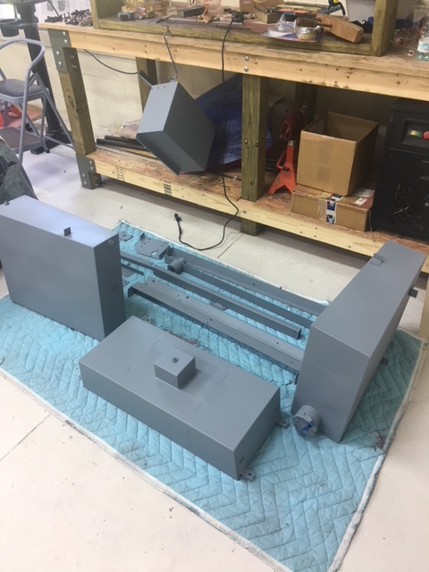
Kit # 10 comprises of two water tanks and one fuel tank. Steam Traction World made these tanks out of Stainless Steel, which is great! They realized that the added expense was well worth it and I agree. I live in a place that experiences high humidity, salt air and it is not uncommon for all of this to condense on to our cars, in our fuel tanks etc. With the introduction of ethanol into our fuel many of the boats around hear have water in their tanks and it is just a mess. So the condensation is an issue. We will have a choice of fuels and I am leaning to diesel. It is readily available and safe.
The first step was to clean and degrease the tanks for priming. I used multi-marine primer from Epifanes -- a company from Holland.
Then I sprayed painted the gloss black mono-urethane paint - again from Epifanes.

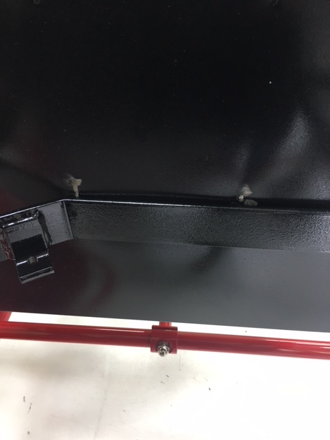
After letting the paint cure for about two days I tried to fit the tanks into the frame, however I had some fit issues. As Steam Traction World warned us in the instructions, the welding of the Stainless Steel material produced a fair amount of distortion as evident below from the scratching of the paint.
The issue here is two fold. One, the tank is rather bowed outwards from edge to edge and two, the angled flange that bolts the cross member to the side rail was slightly non-perpendicular. I took my right angle flapped sanding disk to remove some material to true up the flange. See the shiny two raw steel edges below.

This allowed some additional clearance. I also took my plastic/rubber hammer and gently coaxed the bowed tank flat, with possibly a small amount of indention. I did this on both of the narrow sides - opposite to each other on the lower sections that passes through the frame. Luckily the other side tank only needed the tank bow removed from the narrow tank sides. So again I test fitted the tanks and discovered a few more issues. The welds on the large flat side next to the interior flange for the boiler was hitting - an interference fit. So I took the tanks out again and with my right angle sander smoothed away some of the weldment. The following images shows the final test fit after sanding down the weldments.

On this trial fit I discovered that the tank flanges that seat the tank against the side rails will need a little adjustment as noted with the blue tape. These flanges need to be tweaked down a bit and also I'm considering placing some welt or rubber material under them to provide a little cushion if space will allow. Now the tanks are ready to have their final coat of paint to repair the scratches etc.
All tanks having scratches etc. have been repainted and installed. It appears though that I will have to remove the two back water tanks later to attach the side panels for the final time. That won't be for months and months.
For the fuel tank (lower front tank) we were instructed to use M6 (6mm) bolts and washers, however the mounting holes were actually drilled for M8's (8mm). I used M8 x 20mm hex bolts with washers and a lock washer too (see below).
The water tank without the fill tube appeared to have the two flanges that rest on the side rail chassis member located a little off, making the tank tilt to the side just a bit. I took a level to the tanks along the sheetmetal right angle bends and decided that this tank needed to be trued up. I had some rubber flat stock and I cut two rectangles and glued them with 3M super weather-strip adhesive to the side rails.

The other tank with the filler tube was tilted slightly forward so I used again a piece of rubber to shim this tank too.
And final assembly of the tanks!


The next two pictures shows the clearance of the two rear water tanks to the red painted leaf springs. As they say "a miss is as good as a mile" 

And the final picture where I have just loosely attached the side plywood panels for safe keeping.
Can't wait for the next kit to arrive. I believe it will be one of the three engine kits. And finally I couldn't resist and I penciled in some louvers and trim molding on a print of the above image that I'm trying to figure out. See below.

Popular Posts