

The first step was to clean and degrease the tanks for priming. I used multi-marine primer from Epifanes -- a company from Holland.
Then I sprayed painted the gloss black mono-urethane paint - again from Epifanes.

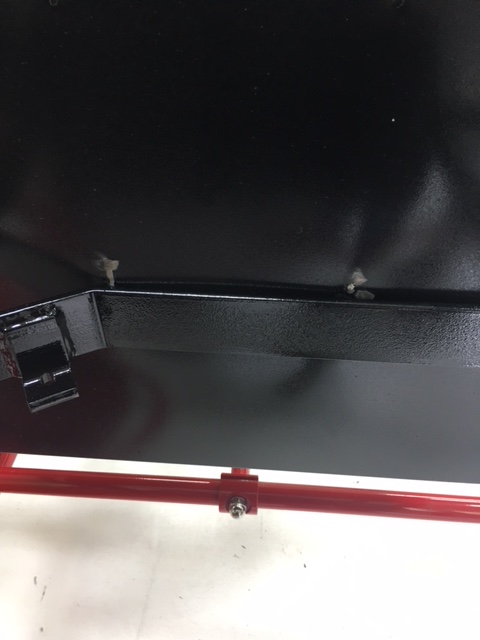
After letting the paint cure for about two days I tried to fit the tanks into the frame, however I had some fit issues. As Steam Traction World warned us in the instructions, the welding of the Stainless Steel material produced a fair amount of distortion as evident below from the scratching of the paint.

The issue here is two fold. One, the tank is rather bowed outwards from edge to edge and two, the angled flange that bolts the cross member to the side rail was slightly non-perpendicular. I took my right angle flapped sanding disk to remove some material to true up the flange. See the shiny two raw steel edges below.

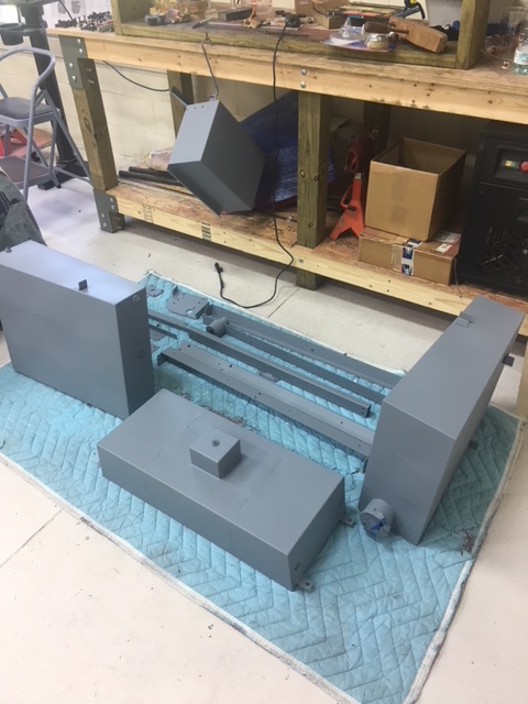
This allowed some additional clearance. I also took my plastic/rubber hammer and gently coaxed the bowed tank flat, with possibly a small amount of indention. I did this on both of the narrow sides - opposite to each other on the lower sections that passes through the frame. Luckily the other side tank only needed the tank bow removed from the narrow tank sides. So again I test fitted the tanks and discovered a few more issues. The welds on the large flat side next to the interior flange for the boiler was hitting - an interference fit. So I took the tanks out again and with my right angle sander smoothed away some of the weldment. The following images shows the final test fit after sanding down the weldments.

On this trial fit I discovered that the tank flanges that seat the tank against the side rails will need a little adjustment as noted with the blue tape. These flanges need to be tweaked down a bit and also I'm considering placing some welt or rubber material under them to provide a little cushion if space will allow. Now the tanks are ready to have their final coat of paint to repair the scratches etc.


All tanks having scratches etc. have been repainted and installed. It appears though that I will have to remove the two back water tanks later to attach the side panels for the final time. That won't be for months and months.

For the fuel tank (lower front tank) we were instructed to use M6 (6mm) bolts and washers, however the mounting holes were actually drilled for M8's (8mm). I used M8 x 20mm hex bolts with washers and a lock washer too (see below).

The water tank without the fill tube appeared to have the two flanges that rest on the side rail chassis member located a little off, making the tank tilt to the side just a bit. I took a level to the tanks along the sheetmetal right angle bends and decided that this tank needed to be trued up. I had some rubber flat stock and I cut two rectangles and glued them with 3M super weather-strip adhesive to the side rails.


The other tank with the filler tube was tilted slightly forward so I used again a piece of rubber to shim this tank too.

And final assembly of the tanks!


The next two pictures shows the clearance of the two rear water tanks to the red painted leaf springs. As they say "a miss is as good as a mile"
And the final picture where I have just loosely attached the side plywood panels for safe keeping.

Can't wait for the next kit to arrive. I believe it will be one of the three engine kits. And finally I couldn't resist and I penciled in some louvers and trim molding on a print of the above image that I'm trying to figure out. See below.


No comments:
Post a Comment