
One modification that I detailed in a previous posting of adding a bracket was not as clear as I could have made it. Below I have annotated the installed bracket for the Valve Chest Blow-off valve. This modification was done really just for convenience for removing the floorboard. Previously the Blow-off valve was mounted directly to the floorboard and not to this metal bracket.

The next modification that was needed was for the chain tensioner. Steam Traction World did not provide any instructions for the mounting of this tensioner, but it became very evident that you need to hacksaw off as much as possible the stud that mounts the tensioner closest to the drive sprocket. If you don't reduce the profile of this stud, more than likely your chain will catch the stud and I can imagine catastrophic events might occur.

A final touch for the floorboards was installing the brass plates that will go around the brake and accelerator pedals.


When I first steamed the boiler, I found leaks here and there. The first being from the water pump packing. Steam Traction World provided holes in the fitting where a small allen wrench can be used to crank down on the packing to seal the shafts from leaking water.


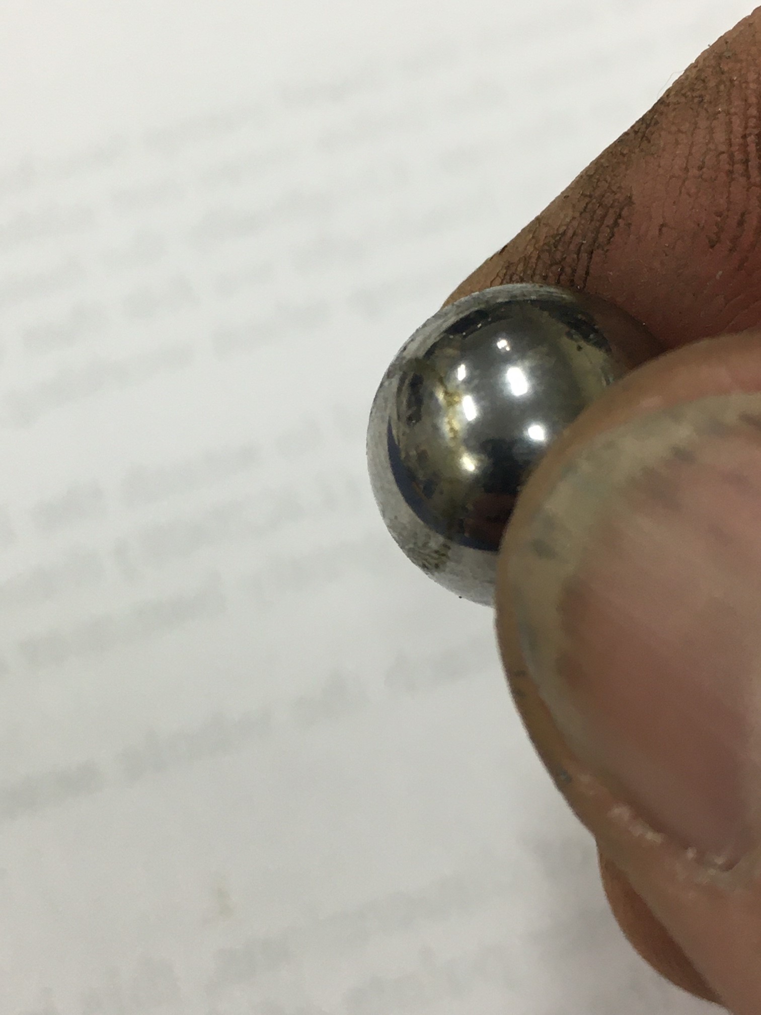
Next I noticed that when the boiler was pressurized, the boiler water infeed check valve was allowing pressure to leak by the check valve causing the water tanks to gurgle. So I took the check valve apart to see if there was anything preventing the check ball from seating properly. What I found was that the check ball was coated with oily sticky residue. So I cleaned this up. It helped but did not completely eliminate the issue. I am going to monitor this to see if the check ball and the brass mating surface will work its way to a good seal. If not then I believe I will have to take some valve lapping compound and figure out a way to lap the valve seat.


Dirty and sticky residue.
All Cleaned
My next issue under steam was that the body for my boiler sight glass sprung a leak.

Front side of the sight glass gauge.
Back side of the sight glass gauge with streaming hot water.
I attempted to repair the pinhole leak, however after trying a bit by drilling and welding the hole, it became evident that the block had an internal material flaw and the crack was bigger internally than I felt comfortable with trying to repair. Steam Traction World sent me a new block as the fix and all is good now.


I ran the steam car several times and the performance in reverse is so much better than forward. Steam Traction World says this is an inherent design feature of the modified Hackworth valve system, but something was just not right. In my case I was getting a lot of vibration in forward and eventually my engine started to jerk in forward like it was trying to pop a wheelie. I attempted to re-time the valves several times, but ended up with the same results. It also started to develop a knock, but the knock turns out to be a separate issue which I will cover later. So once again I seek advice from Dean of Steam Traction World. Dean again reassures me that this can all be worked out and asks me to check the cranks to make sure everything is looking proper and that Ian, his steaming expert would give me a call the next available day. Ian looks over my pictures and tells me that I needed to reset one crank. It appears that I assembled the crank slightly off or the crank shifted somehow to possibly cause a timing issue. Ian explained over the phone how to do the timing again which I followed. Below is the picture of the crank showing the shift in the key and crank.

The other side had not shifted as can be seen below for comparison.

Once I loosened up everything and reset the crank and key, I re-timed the valves again. The procedure is as follows. First you need to place the reverser arm in the forward most position (third notch).

Loosen the reverser control rod and adjust the arms as close as you can without hitting the counterbalance portion of the crank. You don't want the arms to be rubbing the counterbalance.

Once this is done, turn the engine by hand to Top Dead Center (TDC) and adjust the valve slide so that it just begins to crack open. Repeat this step at Bottom Dead Center (BDC). Verify that the TDC crack is about the same opening size as the BDC crack. Keep repeating the adjustments until both the TDC and BDC cracks are as equal in size as possible. Do this for both valve slides.

Following images shows the cranks at TDC and BDC with the valve slides and their equalized openings.


After making all of these adjustments, the steam engine ran much smoother in forward. I was able to test it up to about 20 mph. It might go faster, but I'm pretty satisfied with it at that speed.
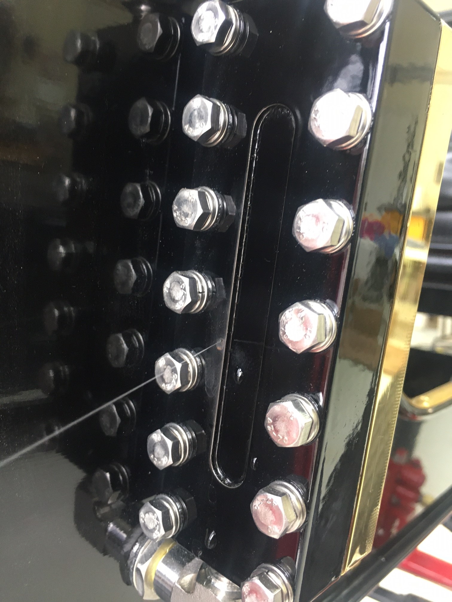
I mentioned earlier that a knock started to develop. I believe I know where it is coming from and unfortunately I believe that my driver's side engine cylinder block has loosened from the mounting frame plate. I can see the whole block assembly rising and lowering with the crank. Below is a picture showing the two plates (lowest two parts in the picture).

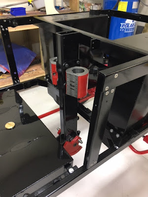

These mount with 4 flat head screws onto the cylinder block as shown in the following picture.

And then this assembly is mounted to the engine beam.

Because the flat head screws are hidden between the flange and the engine beam, I will have to disassemble one side of my engine to get to these screws. I have not done this yet and I am hoping I might just be able to unscrew the four bolts on the flange and rock the assembly over a bit to get an Allen wrench in there to tighten the bolts and place some thread lock in there too. But it must be done.
Finally I am working on an Emergency Boiler Shut-off for a low water safety feature. I do not want to ever cook my boiler again. I believe I can make a system for about $200 which will be cheap in comparison to ruining a $5000 boiler. Once I have worked out the design I will make a posting on this modification with a parts list.
Happy Steaming !!


No comments:
Post a Comment