
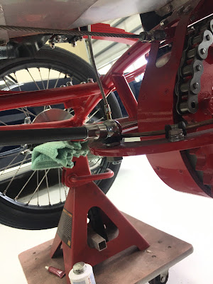
This next posting isn't part of the last kit. It shows the final hook-up of the Speedometer Cable from the front modified brake disk to the speedometer. I had some leftover leather and I fashioned a flexible fitting to hold the speedometer cable conduit. Below are images.


Kit # 22 all unpacked, parts checked and ready to go.

My first task was to sort out the placement of the pressure gauge. Steam Traction World suggested to mount the pressure gauge to the angled floor board because they felt mounting the pressure gauge to the dash board would result in a lot of vibration making the gauge difficult to read. That may be true, but in the original Locomobile, the gauge was mounted vertically towards and in front of the right side of the dash. Because I have created a little dash, I am going to mount the pressure gauge on it. The copper tubing sent by Steam Traction World regardless where the pressure gauge is mounted needed to be carefully re-bent due to it being bent up for placement in the shipping box.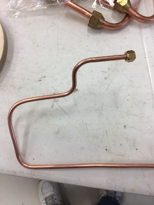

The instruction don't really say where the pressure tube is connected, however the only logical place for it could go is to the T-Fitting on the Pressure Switch mounted on the right side panel of the body.


The copper tubing is formed and placed to the general location for my pressure gauge on my small dash. I layout the location to mount the brass fitting with the supplied paper template. I drill the appropriate sized holes and mount everything.


This involves taking the cable out from its protective sleeve, mounting the cable guide bolt and threading the cable through the cable guide bolt.


Now you are supposed to put the round plug into the throttle actuating arm. In my case the round plug was just a few thousands of an inch too big. I had to open the throttle actuating arm hole up a bit with a properly sized drill bit.
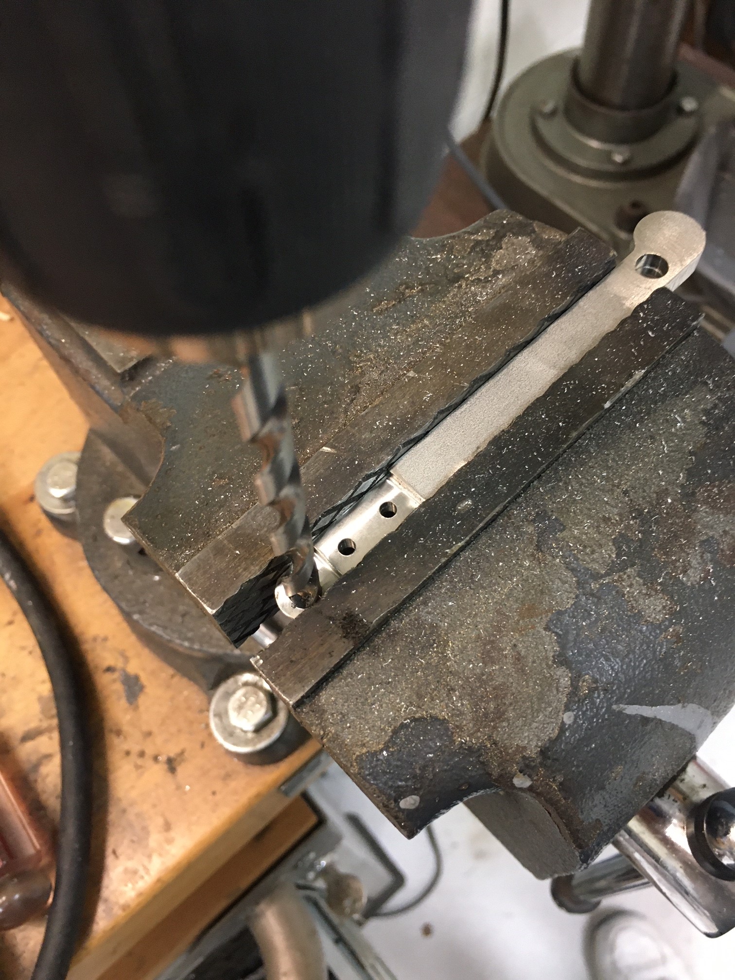

Next I replace the protective outer cable sleeve onto the cable and fish the cable through the chassis towards the accelerator pedal.


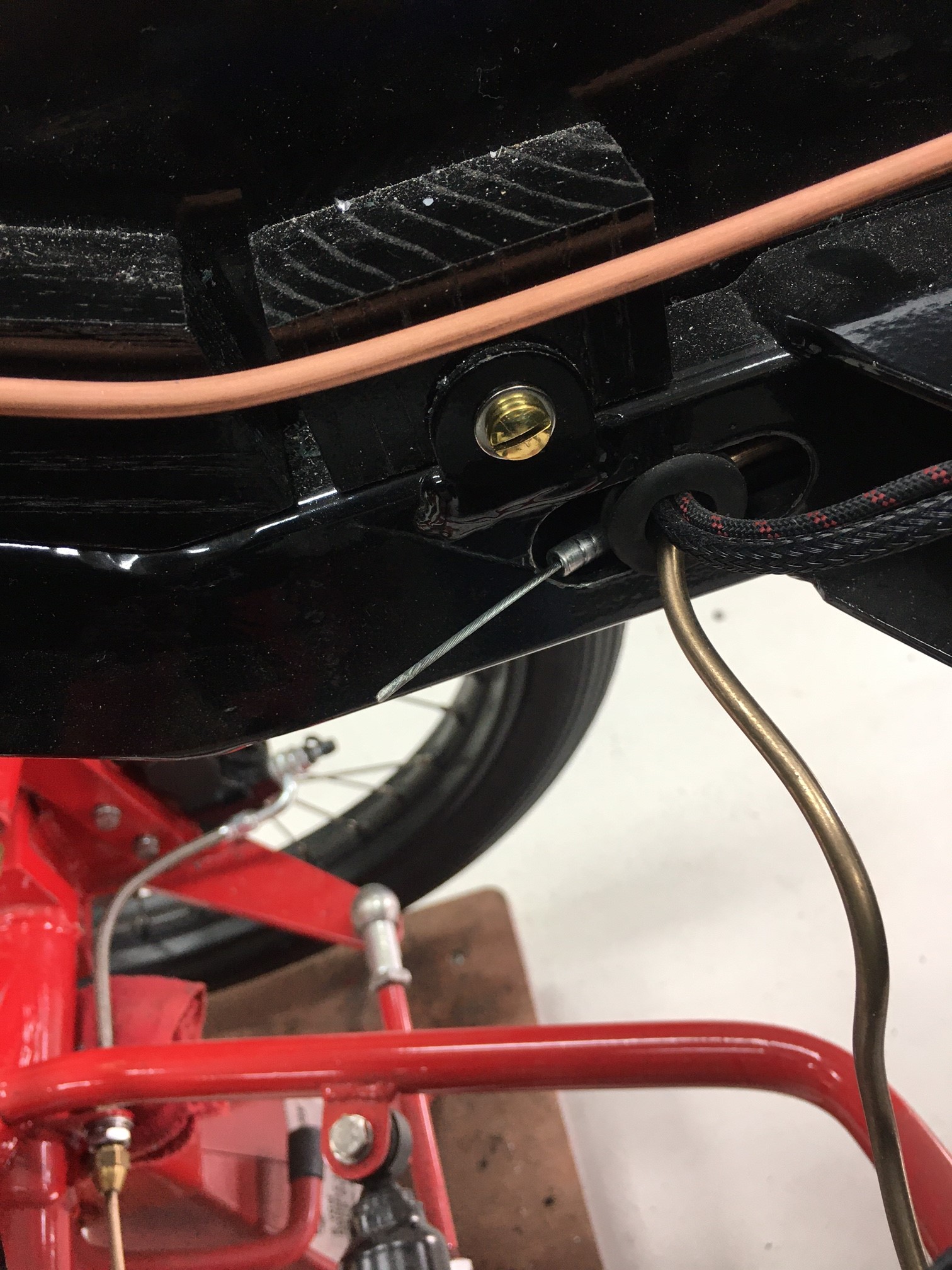
Next I mount the cable bolt guide and thread the cable through it towards the pedal.


The pedal hardware and spring return bracket and spring are mounted next and adjusted.


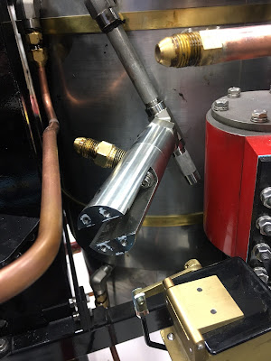



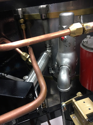


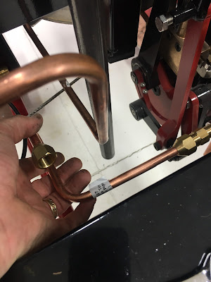

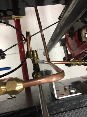


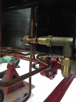
 And a final picture of all the plumbing completed !!




Steam Traction World has made a design change and has instructed us that an additional supporting bracket is needed to beef up and reduce the possible vibrations that might occur to the steam throttle regulator. The following images depict the work and mounting of the new bracket. First the throttle cable flange needs to be temporarily unbolted. 


Next the flange is set in position for marking, hack sawing, drilling and mounting.
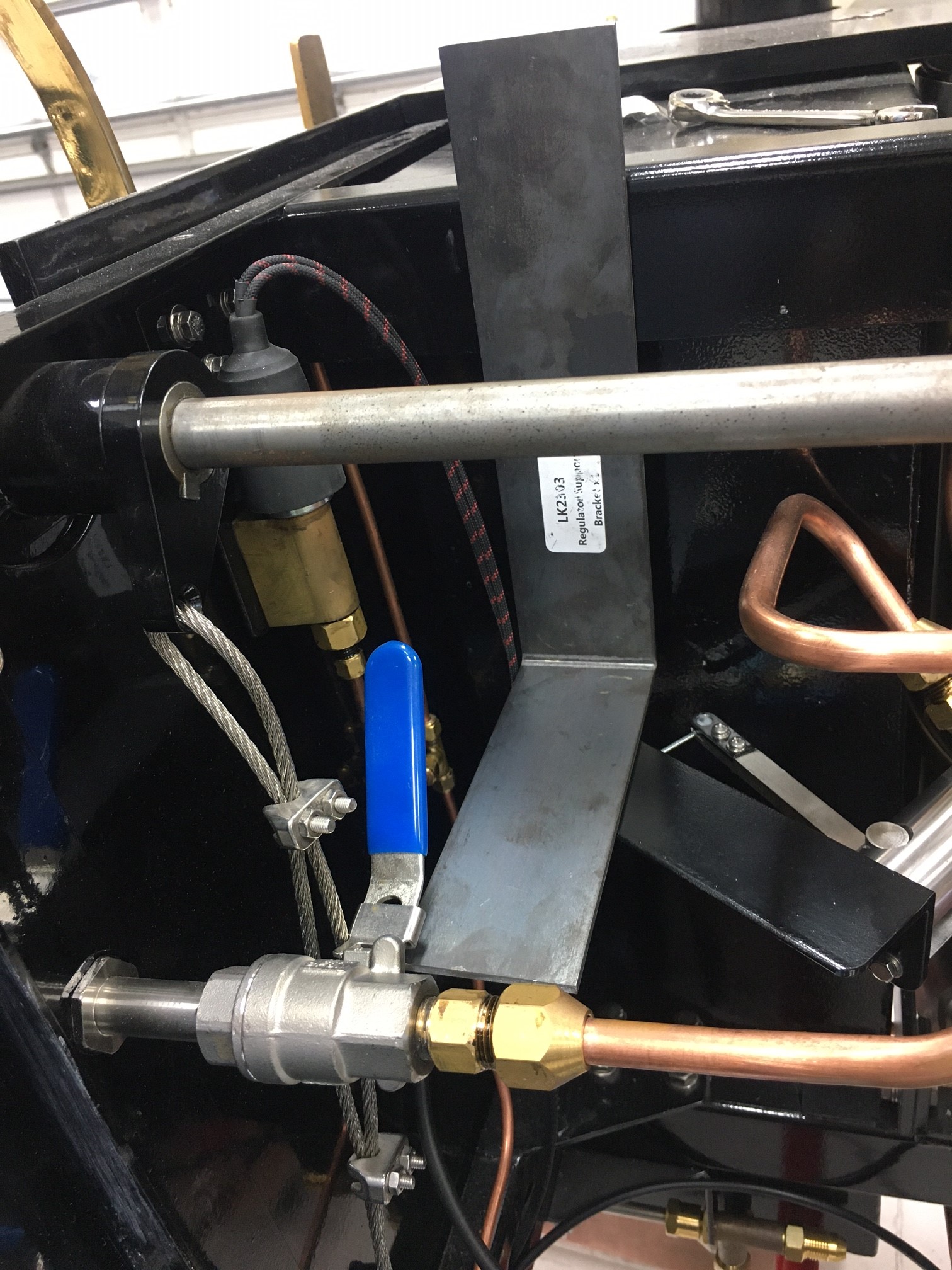


Of course this bracket will need to be painted. The next task is to mount the sight tube for the water tanks. In my case because I have mounted a pair of lights to the sides of the Lykamobile body, this necessitated a bit of a challenge. Unfortunately the sight tube location was interfering with the side light and I had to bend and move the sight tube forward to avoid the lamp. No worries it all worked out as seen below.


Now for final assembly.


The next task was to assemble the pressure relief valve and fittings. I guess hindsight is always clearer, but boy would it have been good if we had received all of this in a much earlier kit. I hate doing negative work and on top of this Steam Traction World failed to provide the Isometric Drawing showing how the parts should go together. Not that anyone could figure this out, but it should have been included with a bit more instructions. Below are the parts laid out showing how it should be fit together.


Now all that work on the steam throttle cable, steam regulator needs to be disassembled to allow access to where the pressure relief valve goes. As you will see, the piping from the boiler will need to be moved over so that the elbow can be screwed on. Also the steam throttle will need to be removed completely to allow the pressure valve to be screwed on too. See the images below:


My next task is to fit the oiling tubing that goes from the oil pumps to the valve chambers. This is pretty straight forward but a big word of caution - make sure you assemble the one way check valves the correct way. The valves have no markings to show the way the oil flow should go. You have to blow on one side of the check valve to verify the direction and then not confuse the direction when you assemble everything. I had them backwards at first and this would have been disastrous if left. No oil to the valves/pistons would not be good. Double check your work.

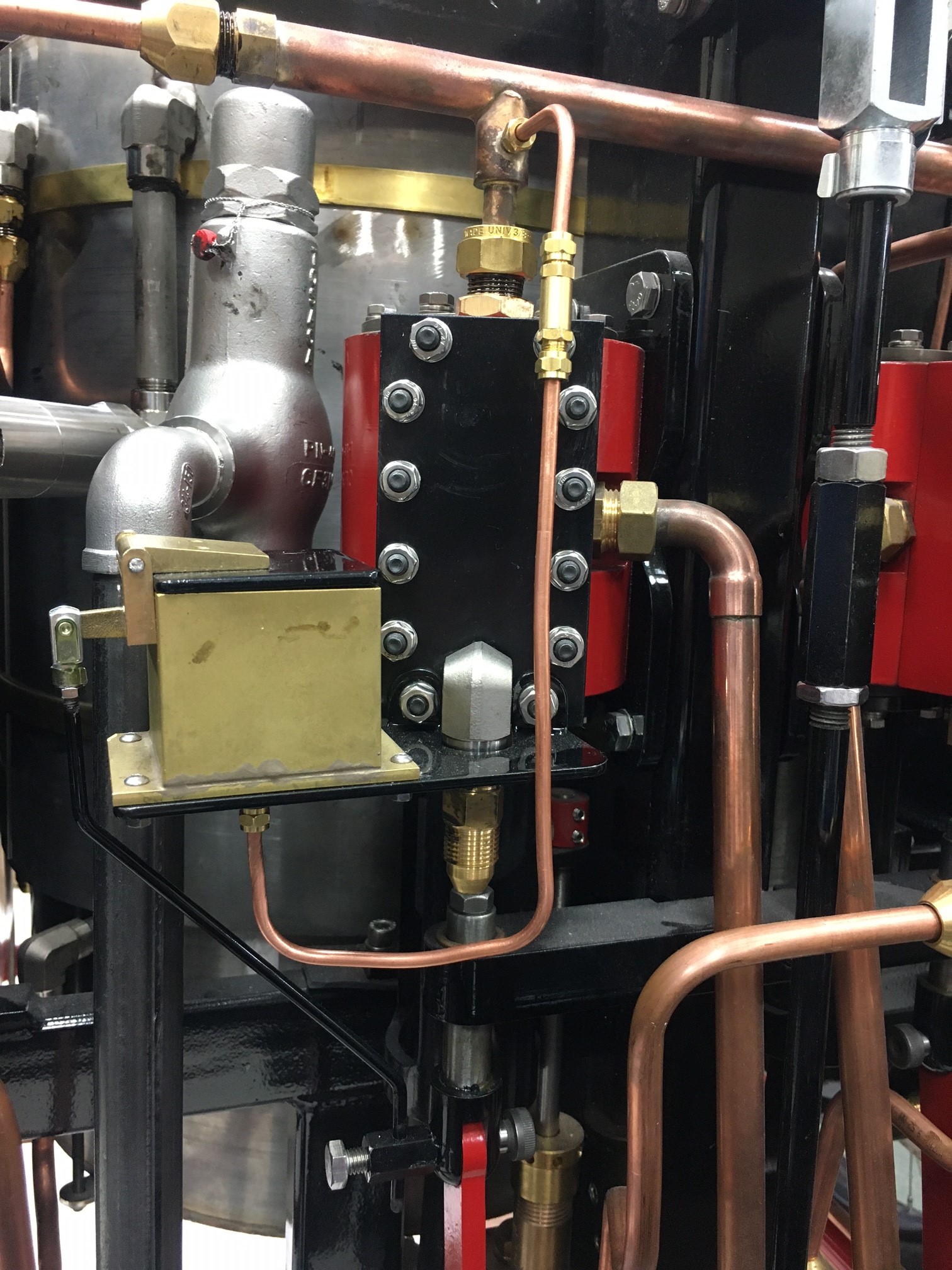
The final work on the plumbing is to install all the tubing for the blow-off valves.

I test assembled everything first for fit and discovered that the Isometric Drawing for two of the parts was wrong. Steam Traction World made a design change, but failed to update the drawings. Once I figured this out everything went together with only slight adjustments to the tube bends.


The next few images shows where the drawing was wrong. Below is how the two copper pipes should be assembled to this valve. Steam Traction World had completely different looking parts in the drawing and had the copper pipe's locations reversed.


The final assembly I used the Teflon Tape on the brass T fitting. Hopefully this is correct to do. I don't expect the temperatures to get that high here, so it should be okay.

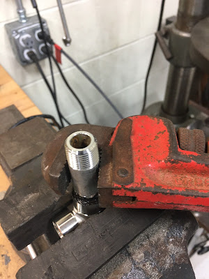
The final blow-off valves are fitted to the boiler. Unfortunately way back when Steam Traction World sent us some of the boiler fittings they used a fine thread fitting. Later they decided to replace these fittings with a coarse thread. I thought I had replaced all the fittings, but I discovered much to my chagrin a fitting that had not been changed. And this fitting required me to lift the right tank up to access it. I probably would have had to lift the tank up anyway to tighten the copper pipe attachment anyway - AGAIN negative work. Below are the images for this exercise.


The very last thing to do is to figure out the Chain Tensioner. Steam Traction World had nothing in regards to instructions or drawings for this except a note that directions were to follow. But how difficult could this be? Below are the parts test fitted.

This assembly should be mounted between the engine frame and the differential frame. The following shows it test fitted on the Lykamobile.


I believe in the above photo that the nut should be the jam nut instead of this regular nut and that the protruding stud should be cut flush with the jam nut. The chain passes over this area and it would be catastrophic for the chain to catch on this protruding stud. I guess I will wait for instructions from Steam Traction World in this regard.

My next posting will be showing an air pressure testing of the engine and a few additional modifications to the mounting of one of the blow-off valves and miscellaneous other details.


