

Outer Bearing Race
Positioning outer bearing race.

Tapping the bearing race into the hub.


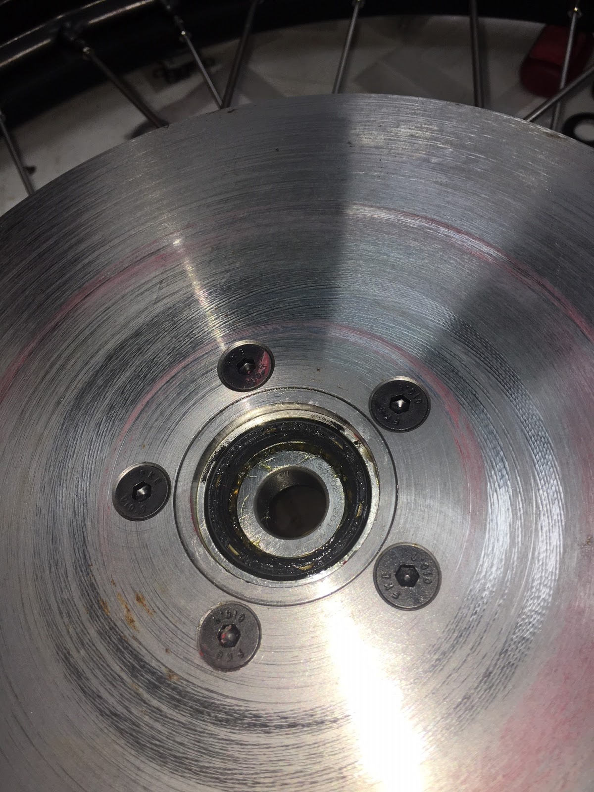
Next I place the Front Hub Spacer aligning all the holes to the M6 tapped holes.

And then I place the Brake Disc aligning the holes. (Later I will change out for Stainless Steel and apply some medium thread lock on them)

And temporarily fixing the disc with five M6 Csk Flat Head Screws.


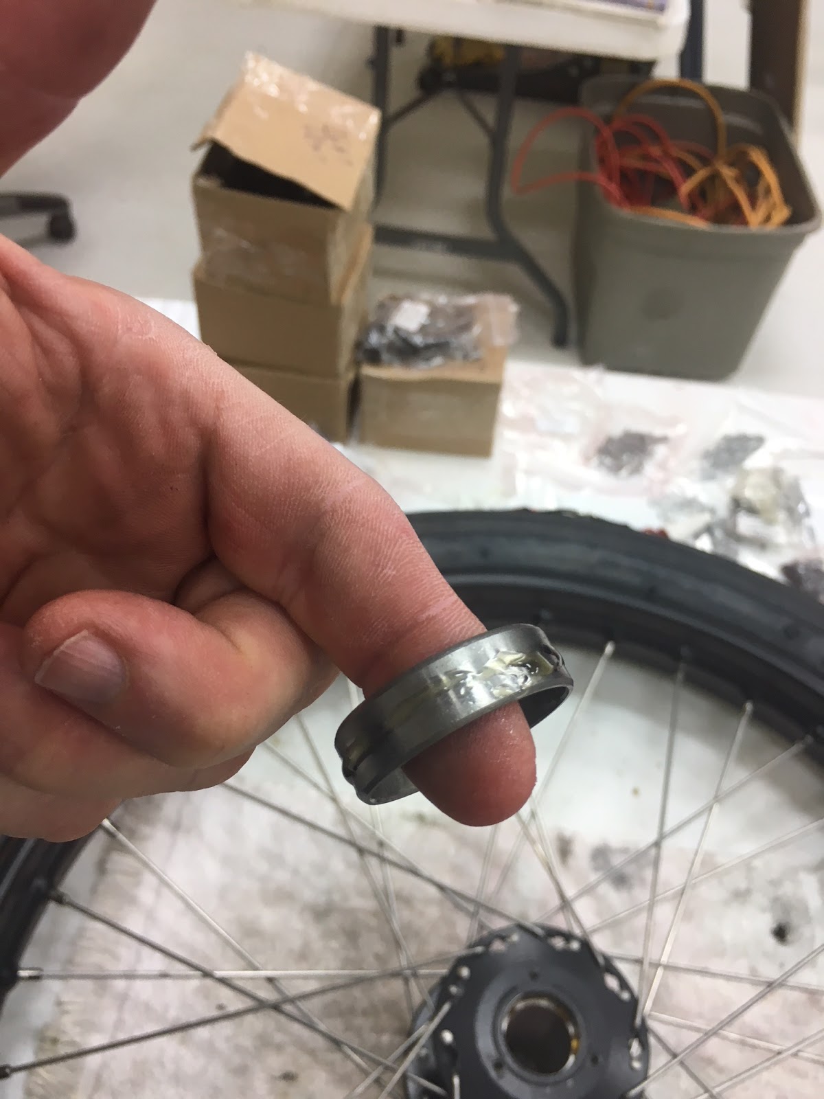
Now it is time to pack the bearings with grease.


Then you need to place the inner hub wheel bearing into the hub and press the Grease Seal next into the inner hub. Don't press the seal too far into the hub. This will impede the bearing from rotating. I placed the seals flush with the hub.
Inner Bearing placed into the Hub.

Next trial assemble the wheel to the front wheel spindle.


And here we go !! HUH OH ! A slight interference fit with the brake disc to the steering spindle weldment.

No worries, bring out the flap sanding disc right angle drive and away it goes.

Test assembled it again.

Next I test assemble the disc caliper. And even though Steam Traction World made an adjustment to the Front Hub Spacer the disc pads on the inner side where very tight.

In fact I decided that the Front Hub Spacers needed to be faced off another 0.020 inch (0.5 mm). I took the hub spacer to a local machine shop to have this done. In retrospect I believe I could have taken another 0.015 inches off and this would have been better. I reassembled the front wheels and retested everything. The wheels still dragged a little on the disc pads. This would wear clear eventually, but I decided to make a few more modifications to allow me to adjust the caliper alignment better to the disc. The first thing I did was to grind/file off the counter bored holes on the calipers.
Counter-bored holes on Calipers

Counter-bored holes filed off.


And I opened up the mounting holes to about 11.5 mm (from 10 mm diameter). I made some thick flat washers/spacers to place over the mounting nubs on the steering spindle. This provides more surface to mount the calipers.


Mounted caliper.


As you can see, I now have some daylight on both sides of the brake pads next to the disc.

And the wheels spins with just a slight ring to it from the disc not being totally flat or parallel to the spindle axes, but pretty darn good.
And the final touch assembly of the hub cap.

And below you see I have modified the right disc by Wire EDM (Electro-Discharge-Machining) a gear tooth profile for driving a Model T Speedometer that I plan to install later.


Now that everything is assembled I did unscrew the flat head steel screws on the two front discs and replaced them with stainless steel flat head screws. I added a touch of medium strength thread locker to the middle of the threads. I thought that I really didn't want to glue the whole length of the thread because it might be a difficult task removing the screws someday. In this case less is better.
And the final product of Kits 1 through 7.


If you been following my post on facebook likamobile, then you know about the rear end gears failing on my lika. still don't know why they failed. The car only has about 200 miles on it. I will be doing some tests for hardness on the gears. That my give me some clue about them.
ReplyDeleteone other item about the speedo on the early cars they did not use a swivel on the wheel gear, that was introduced around 1908 or after.
ReplyDeletewhat type of display panel for all the parmentiers are you using I heard that STW does not supply a display as in series 1 cars.
ReplyDelete